
Scanner

Inactive Publication Date: 2005-09-15
LITE ON TECH CORP
View PDF2 Cites 9 Cited by
  • Summary
  • Abstract
  • Description
  • Claims
  • Application Information

AI Technical Summary

Benefits of technology

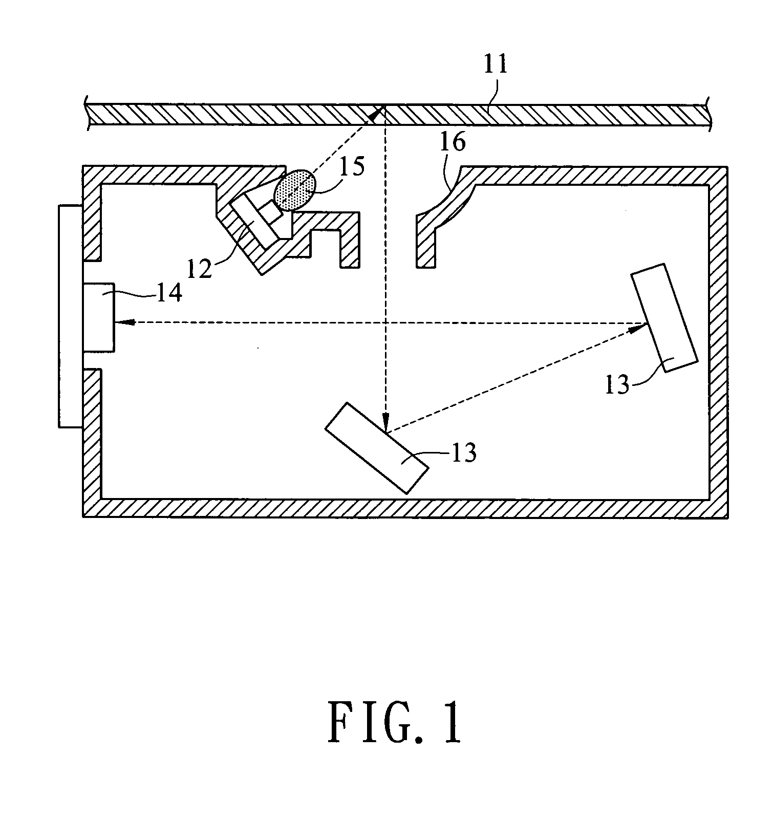
[0012] Aside from the rod lens, to increase the brightness and evenness of the light of the LED lamp set, at least one reflection surface is disposed at a suitable location around the LED lamp set, to gather the scattered light and focus the light to, achieve sufficient and even brightness.
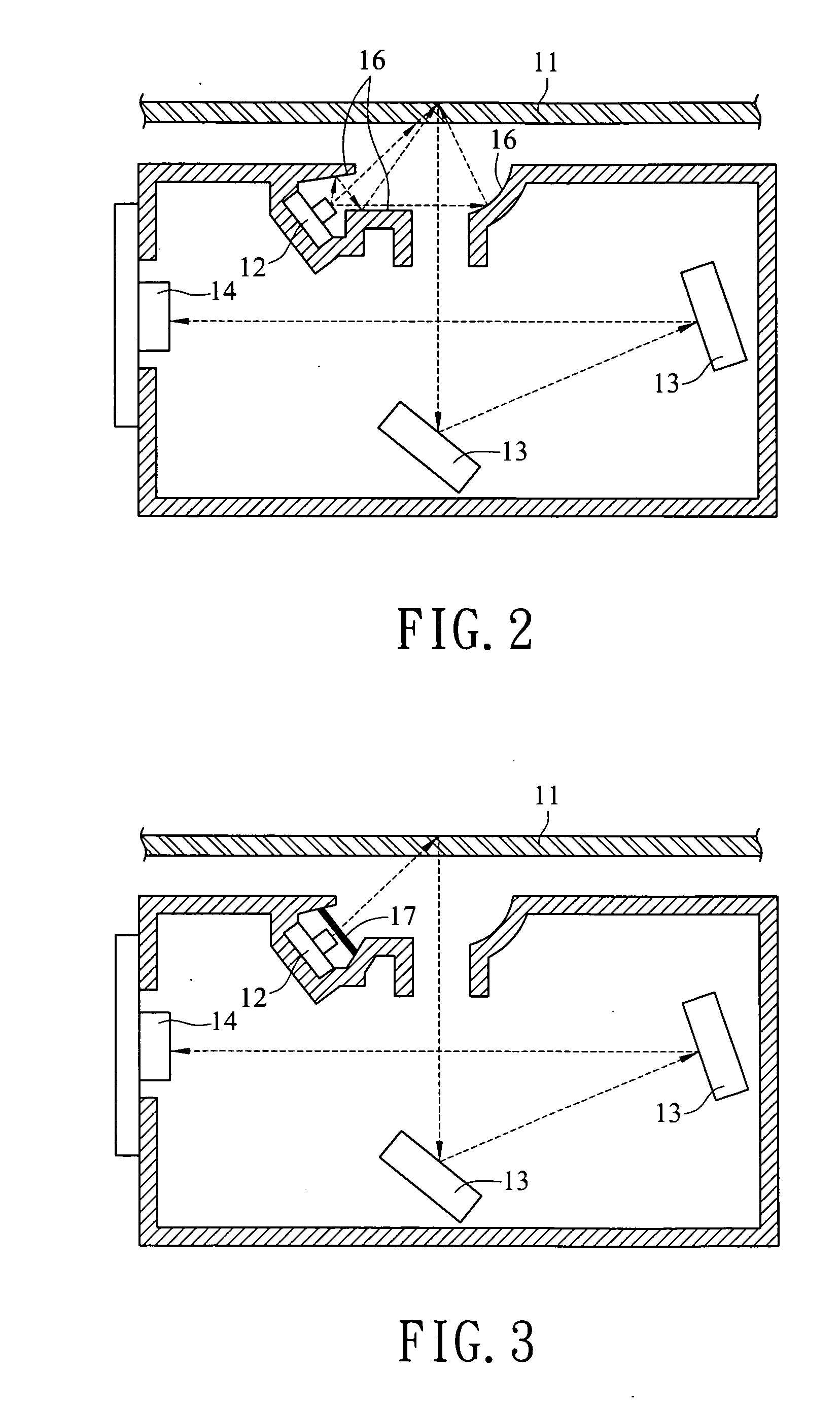
[0013] Moreover, at least one brightness enhancement film (BEF) or diffuser is disposed at a suitable location around the LED lamp set to increase even distribution and brightness of the light emitted from the LED lamp set.

Problems solved by technology

Otherwise the light intensity cannot effectively present the details of the dark portions of the document.
Such a lamp has a big drawback, it requires a warm up time when the scanner is powered on each time to enable the brightness of the lamp to increase to a stable condition.
It is an idling time many users feel is unbearable.
Some users even mistakenly deem it as machine malfunction and request product return.
This is especially significant and serious in a low temperature environment.

Method used


Image

  • Scanner
  • Scanner
  • Scanner

Examples


first embodiment

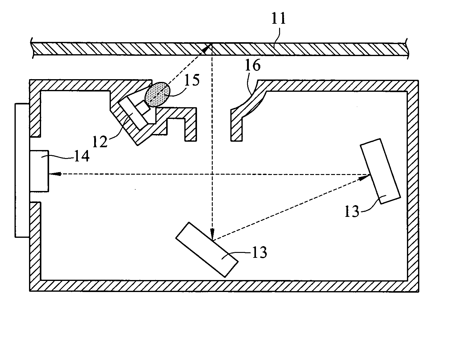
[0019] Refer to FIG. 1 for the scanner of the invention.

[0020] The scanner includes a transparent plate 11, an LED lamp set 12, a reflection mirror set 13 and an image sensor 14.

[0021] The LED lamp set 12 consists of at least one LED lamp to serve as the light source to emit light.

[0022] The transparent plate 11 has one side corresponding to the LED lamp set 12 and another side corresponding to a scanning object (not shown in the drawing). Light emitted from the LED lamp set 12 passes through the transparent plate 11 and projects onto the scanning object.

[0023] The reflection mirror set 13 consists of at least one reflection mirror to reflect and focus the light reflected from the scanning object after having been projected by the light emitted from the LED lamp set 12.

[0024] The image sensor 14 is a charge-coupled device (CCD) to receive light reflected from the reflection mirror set 13, and transforms the optical signals to analog signals to output.

[0025] A CCD is a photoelec...

second embodiment

[0030] Refer to FIG. 2 for the invention. Aside from the rod lens 15, to increase and even the brightness of the light emitted from the LED lamp set 12, at least one reflection surface 16 is disposed at a desired location around the LED lamp set 12 to reflect and gather the scattered light and achieve even brightness.

third embodiment

[0031] Refer to FIG. 3 for the invention. At least one BEF (Brightness Enhancement Film) 17 or diffuser is disposed at a desired location around the LED lamp set 12, to enable the light emitted from the LED lamp set to become more uniform and have greater brightness.


PUM


Abstract

A scanner which replaces CCFL with LED as a light source so as to solve the problem of excessively long warm-up time of CCFL in the prior art is provided. Meanwhile, objects as rod lens, reflectors, brightness enhancement films (BEF), or diffusers may be applied to enhance and even the brightness of the LED.

Description

FIELD OF THE INVENTION [0001] The present invention relates to a scanner and particularly to a scanner that uses LED as the light source. BACKGROUND OF THE INVENTION [0002] The scanner, aside from the keyboard and mouse, is a widely used computer input device. It can be used to input photos to generate personal electronic picture files, or input pictures to set up a personal Web site. Or hand-written letters may be sent by scanning and E-mail to replace FAX machines. The scanner can also be coupled with OCR software to enter contents of newspapers or books without the tedious labor of manual data entry. All this shows the powerful functions of the scanner. It greatly improves the efficiency in offices, learning and recreation. [0003] The scanner achieves its functions mainly by digitizing the picture. Light is emitted from a lamp and reflected to a document held on a glass plate of the scanner. The bright and dark differences of the document form reflection light of different intens...

Claims


Application Information

Patent Timeline
IPC IPC(8): H04N1/04
CPCH04N1/02825H04N1/0318H04N1/02895
Inventor LEE, TA-YICHANG, JUNG-CHIAO
Owner LITE ON TECH CORP
Learn More