
On-site power generation system with redundant uninterruptible power supply

a power generation system and power supply technology, applied in emergency power supply arrangements, dynamo-electric converter control, instruments, etc., can solve the problems of high cost, sub-optimal reliability, and excessive damage to the environmen

Inactive Publication Date: 2005-09-15
ENDUR
View PDF7 Cites 151 Cited by
  • Summary
  • Abstract
  • Description
  • Claims
  • Application Information

AI Technical Summary

Benefits of technology

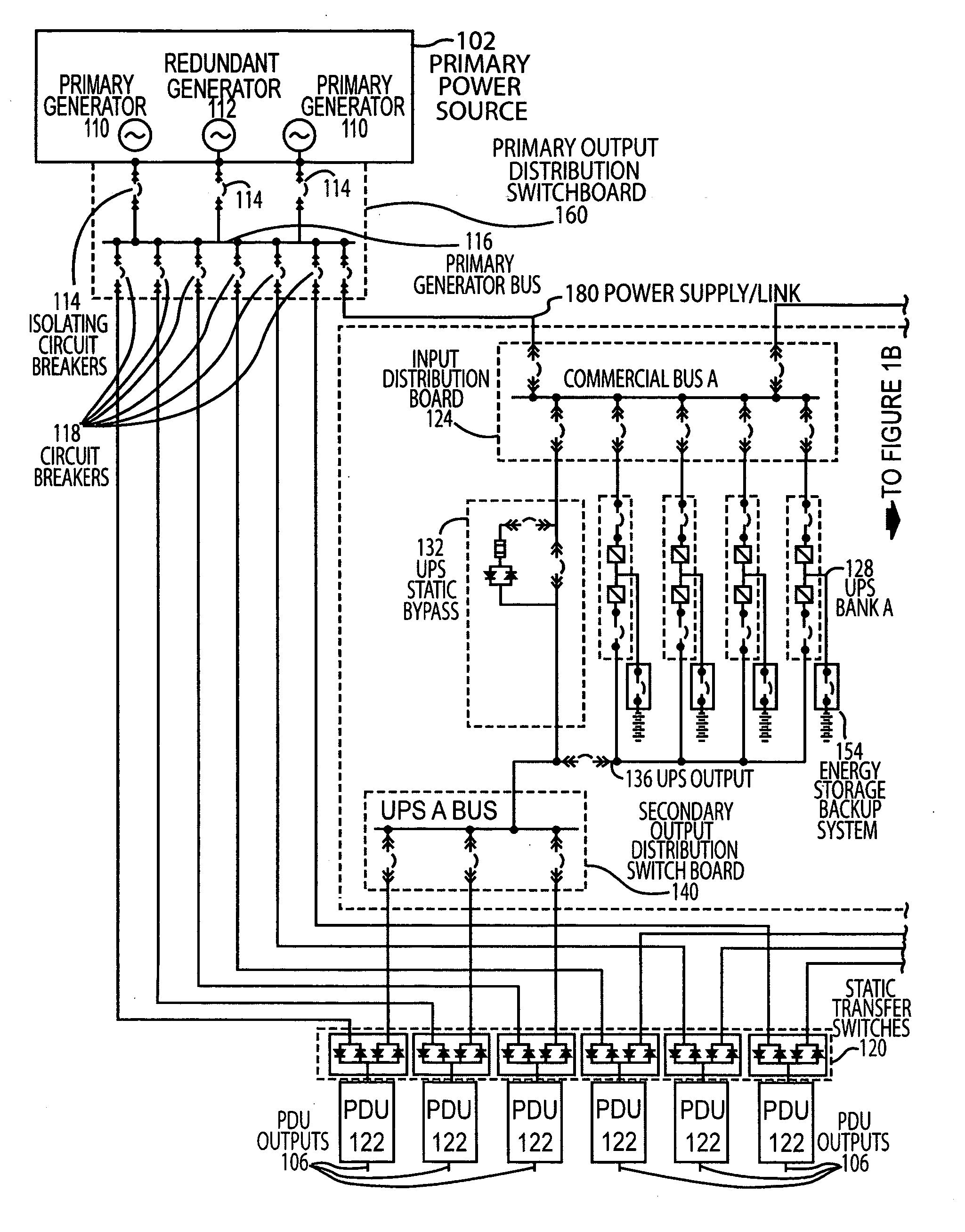
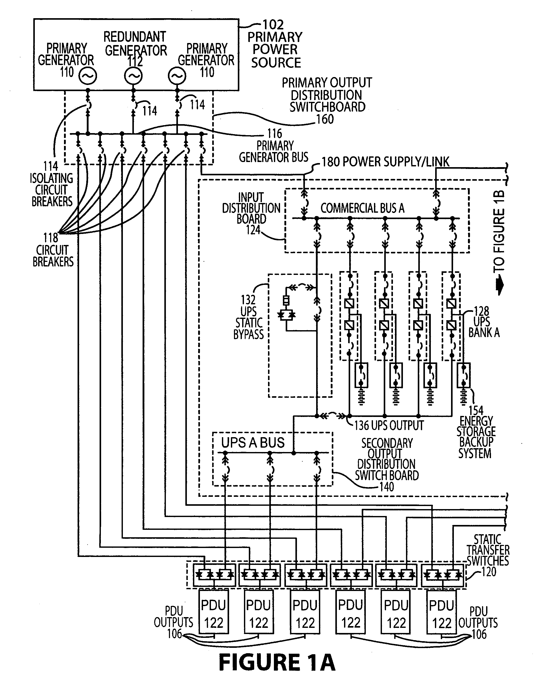
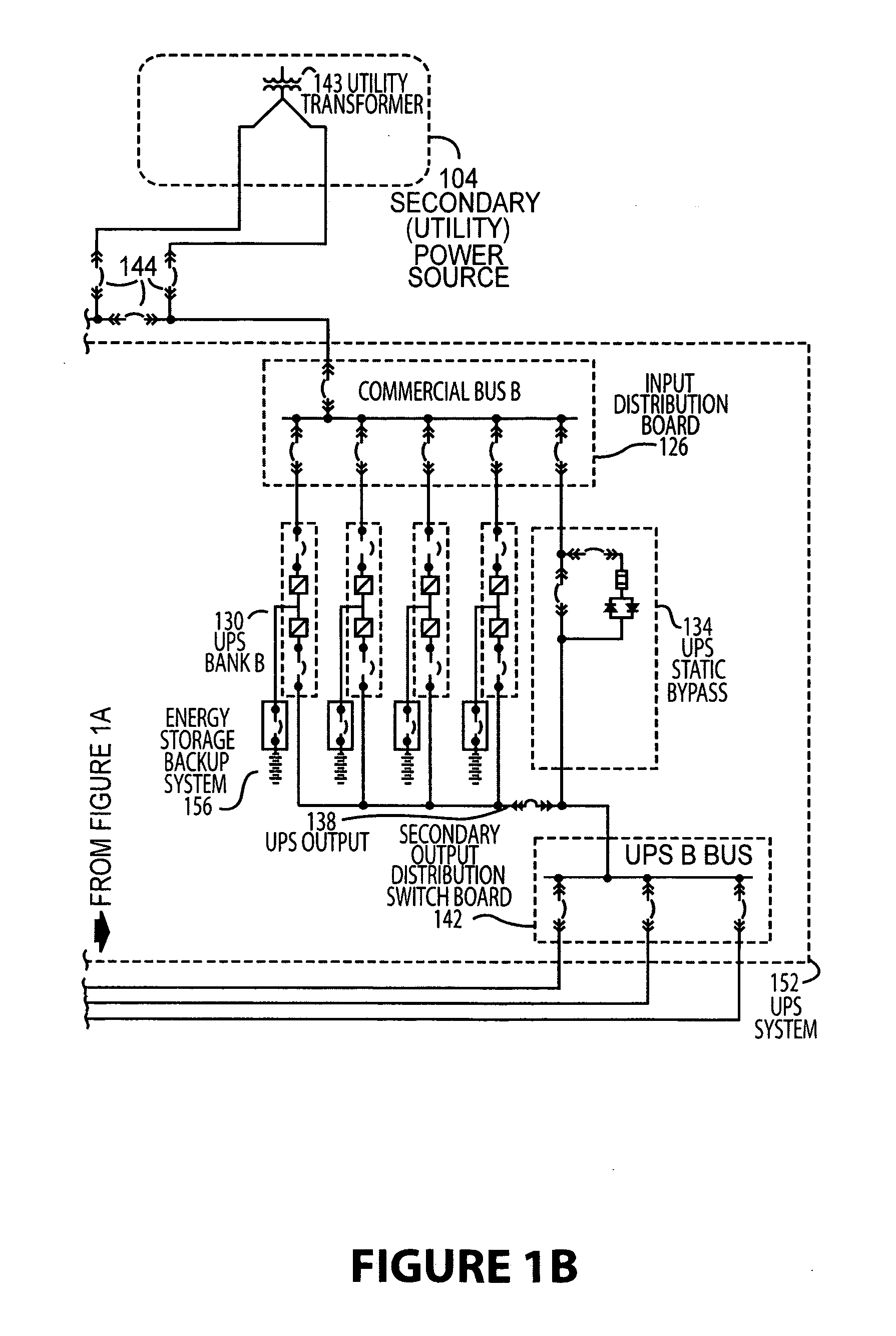
[0007] The present invention may therefore comprise an electrical power generation system comprising: an on-site primary power source that supplies primary power to a primary generator bus; a primary output distribution switchboard that receives the primary power from the primary generator bus and distributes the primary power to a static-switch; a secondary power source that supplies secondary power to an input distribution bus; a secondary output distribution switchboard for receiving the secondary power from the input distribution bus that distributes the secondary power to the static-switch, the static-switch that switches power sources from the primary power source to the secondary power source in the event of a failure of the primary power source; a synchronization control that monitors and compares frequencies and voltage phase angles of the primary power and the secondary power and synchronizes the primary power source and the secondary power source; an energy storage backup system to provide short-term power that enables the secondary power source to be initiated and synchronized into a distributed power grid; and, a power distribution unit that receives power from the static-switch and distributes electrical power to an electrical demand.
[0008] The present invention may also

Problems solved by technology

This widely employed approach results in high cost, sub-optimal reliability, and excessive damage to the environment.

Method used


Image

  • On-site power generation system with redundant uninterruptible power supply
  • On-site power generation system with redundant uninterruptible power supply
  • On-site power generation system with redundant uninterruptible power supply

Examples


Embodiment Construction

[0013] While this invention is susceptible to embodiment in many different forms, there is shown in the drawings and will be described herein in detail specific embodiments thereof with the understanding that the present disclosure is to be considered as an exemplification of the principles of the invention and is not to be limited to the specific embodiments described.

[0014]FIG. 1 illustrates an embodiment of an on-site power generation system that incorporates a redundant power source with back-up power supply. As illustrated in FIG. 1, the primary power source 102 in this embodiment comprises two primary generators 110 and redundant generator 112. The primary generators 110 and redundant generators 112 may take a wide variety of form including natural gas reciprocating engines, dual fuel diesel / natural gas fired engines, natural gas fired turbines, natural gas fired micro turbines, fuel cells or the like. The power from the source is typically generated anywhere between 480V and...


PUM


Abstract

Disclosed is a method and system for providing constant critical AC electrical load with primary, secondary, and in some cases a tertiary source of power with higher reliability and lower operating and capital costs and lower emissions than the traditional utility supply, uninterruptible power supply (UPS), and battery primary power source, and diesel generator back-up systems that are predominately used today. Specifically, the disclosed system utilizes on-site power generation to provide primary power and includes full utility and UPS / DC storage back-up systems.

Description

CROSS REFERENCE TO RELATED APPLICATIONS [0001] The present application is based upon and claims the benefit of U.S. Provisional Patent Application Ser. No. 60 / 540,800 by David W. Winn, et al., entitled “On-Site Power Generation System with Redundant Uninterruptible Power Supply” filed Jan. 30, 2004, the entire contents of which is hereby specifically incorporated by reference for all it discloses and teaches.BACKGROUND OF THE INVENTION [0002] 1. Field of the Invention [0003] The present invention relates to on-site power generation and more specifically to a system that provides full time primary electrical load with multiple redundant backup capability. [0004] 2. Description of the Background [0005] Critical facilities within various financial, information, industrial and military applications require power that is not subject to loss or substantial variability on a continuous, or 24 hour per day, 7 days per week duty cycle. Large-scale computer information systems, databases, cont...

Claims


Application Information

Patent Timeline
IPC IPC(8): H02J9/00H02K7/02H02P11/00
CPCH02J3/42H02J9/08H02J9/066H02J9/062
Inventor WINN, DAVID W.HERNANDEZ, ALFREDO H.CARR, GARY D.
Owner ENDUR
Learn More