
Surgical wound drain tube with flow control safeguards

a flow control safeguard and wound technology, applied in wound drains, suction devices, intravenous devices, etc., can solve the problems of harmful to adjacent organs such as the lungs, fluid build-up in the cavity,

Inactive Publication Date: 2005-09-08
DOLLIVER PHILLIP B +2
View PDF15 Cites 21 Cited by
  • Summary
  • Abstract
  • Description
  • Claims
  • Application Information

AI Technical Summary

Benefits of technology

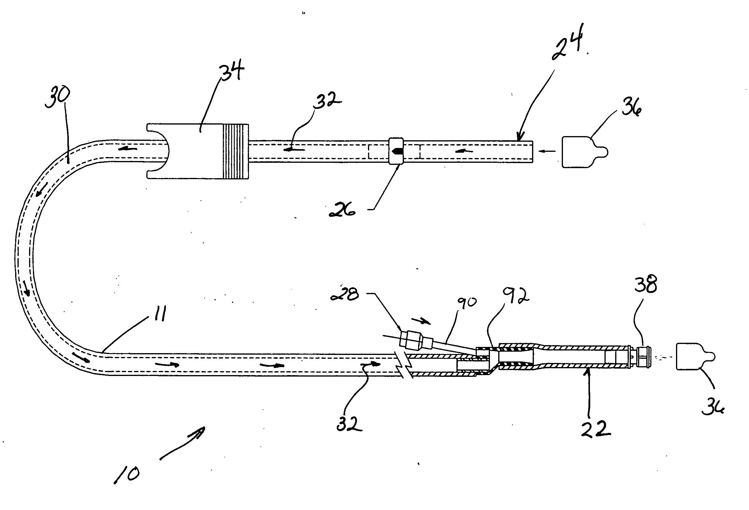
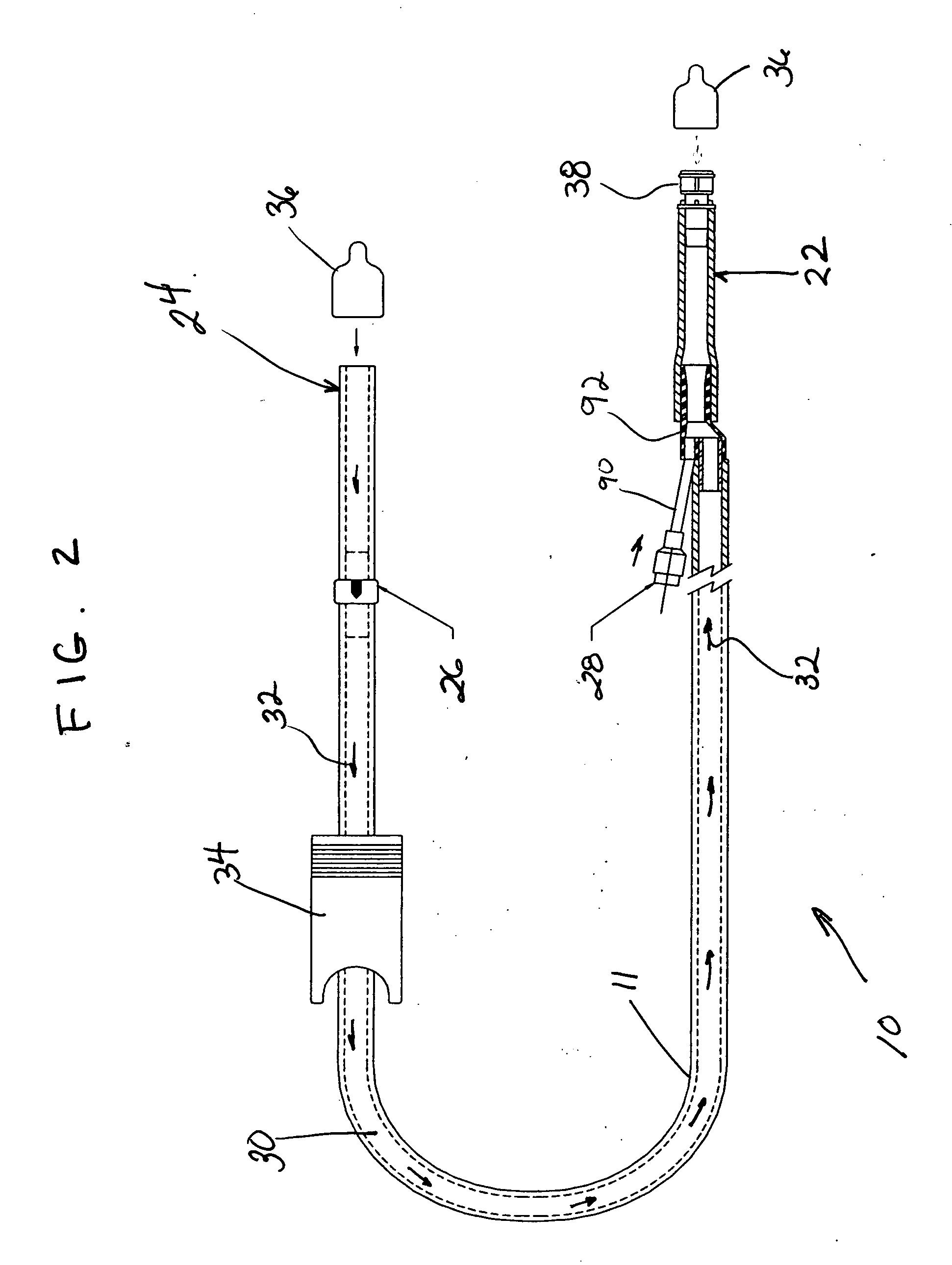
[0006] The present invention provides a surgical drain tube having one or more components that serve to control the flow through the tube in a manner that is safe for the patient and non-disruptive to the post-operative surgical site. In particular, the drainage tube may be configured as a length of tubing configured to extend between a drainage catheter placed at the operative site in a patient and a blood collection device such as an autotransfusion device that can be operated to apply suction to the tubing to remove blood and other fluids from the site in order to promote healing. The tubing is configured with one or more flow control features built into it to ensure that flow occurs only in the correct direction and only at suction levels that are suitable for the surgical site.
[0009] With the anti-reflux valve in place, air and liquid being suctioned from the surgical site will not be free to flow backwards toward the patient if the suction is discontinued. In a procedure carried out in the chest cavity suction is generated as the diaphram moves to expand the lungs. A drain tube in place without such a valve provides an open fluid pathway into the chest cavity reducing suction needed to fill the lungs with air to carry out breathing. Additionally, reverse suction though the drain tube can be generated, drawing in blood and fluids previously drained from the surgical site. At a minimum such an occurrence hampers progress of cleaning the site from contaminants and blood from the surgery, but also fluid build up in the cavity could be harmful to adjacent organs such as the lungs.
[0011] It is the object of the present invention to provide safeguards for controlling flow through a surgical drain tube so that the patient is not injured by undesirable flow characteristics through the tube.

Problems solved by technology

At a minimum such an occurrence hampers progress of cleaning the site from contaminants and blood from the surgery, but also fluid build up in the cavity could be harmful to adjacent organs such as the lungs.

Method used


Image

  • Surgical wound drain tube with flow control safeguards
  • Surgical wound drain tube with flow control safeguards
  • Surgical wound drain tube with flow control safeguards

Examples


Embodiment Construction

[0026]FIG. 1 is a diagrammatic illustration of a surgical drain tube 10 of the present invention extending between the patient 12 and a blood collection device 14. The drain tube may be used with a compact perioperative autotransfusion device 16 such as the OrthoPAT® manufactured by Haemonetics® Corporation and described in U.S. Pat. No. 5,733,253, the entirety of which is incorporated by reference herein. The autotransfusion device may be sufficiently compact to be mounted on an IV pole 18 which is readily available in a hospital setting. The blood collection device 14 is operated to create suction in a fluid collection vessel 20 to which a device end 22 of the drain tube is joined. A patient end 24 of the drain tube is configured to be joined to a drainage catheter in place in the surgical site of the patient 12. Drain tube 10 has one or more flow control safeguards such as an anti-reflux 26 and / or a vacuum relief valve 28 that are in fluid communication with lumen 30 that extends...


PUM


Abstract

Flow control safeguards are integrated into a blood collection system on a disposable component such as the post-operative surgical drain tube leading from the patient to the collection device. One aspect of the invention prevents suction levels that are too high for the tissue and organs adjacent at the surgical site by providing a vacuum relief valve integrated into the drain tube. In another aspect of the invention, reverse flow of fluid back to the patient is prevented by integration of an anti-reflux valve into the surgical drain tubing.

Description

FIELD OF THE INVENTION [0001] The invention relates to devices used to collect blood and other fluids from a patient during and following a medical procedure. In particular, the invention relates to devices and methods for post-operative drainage of fluids from a surgical site. BACKGROUND OF THE INVENTION [0002] Automated devices configured to collect blood and other fluids from a surgical site are common. In a post-operative setting, such devices may be configured as an autotransfusion system that returns collected blood back to the patient after processing and filtering. The collection devices operate by providing suction through a conduit such as tubing that is connected to a drain catheter placed at the surgical area. Blood and fluids are suctioned into the tubing and carried to a reservoir external to the patient. [0003] Though collection of fluids from an internal surgical site is important to the recovery of the patient, there are risks involved with introducing suction to a ...

Claims


Application Information

Patent Timeline
Patent Type & Authority Applications(United States)
IPC IPC(8): A61M1/00A61M27/00
CPCA61M1/008A61M1/02A61M2039/2486A61M39/24A61M2039/242A61M1/3693A61M1/3696A61M1/3698A61M1/84
Inventor DOLLIVER, PHILLIP B.SAUNDERS, MARK EDWARDBOBROFF, ALEC
Owner DOLLIVER PHILLIP B
Learn More