
Electronic revenue meter with automatic service sensing

a technology of automatic service and electronic revenue meter, which is applied in the direction of instruments, data processing applications, sustainable buildings, etc., can solve the problems of manual intervention to determine, equipment typically required manual interpretation, and customer often must program the service typ

Inactive Publication Date: 2005-09-08
ITRON
View PDF5 Cites 42 Cited by
  • Summary
  • Abstract
  • Description
  • Claims
  • Application Information

AI Technical Summary

Benefits of technology

[0023] In addition, the device also periodically checks for other, non-fatal, errors such as for register overflows, clock, time of use, reverse power flow, and low battery errors. The frequency of error checking may vary depending upon the component and...

Problems solved by technology

Ancillary equipment used for this purpose is not intended to become a permanent part of the electric circuit, and it is not adapted to be plugged into a meter socket for such purpose.
Further, while such equipment can be used to measure electric parameters between two or more points, they require manual intervention to determine the points between which such measurements are made.
In addition, such ancillary equipment typically required manual interpretation of the results of the measurements made by their users.
In addition, although there are revenue meters available that may be adapted for use in more than one type of electrical service, one drawback of these revenue meters is that the customer often must program the service type into the meter prior to installation.
This pre-installation programming of multiple service revenue meters tends to limit their multiple service capability.

Method used


Image

  • Electronic revenue meter with automatic service sensing
  • Electronic revenue meter with automatic service sensing
  • Electronic revenue meter with automatic service sensing

Examples


Embodiment Construction

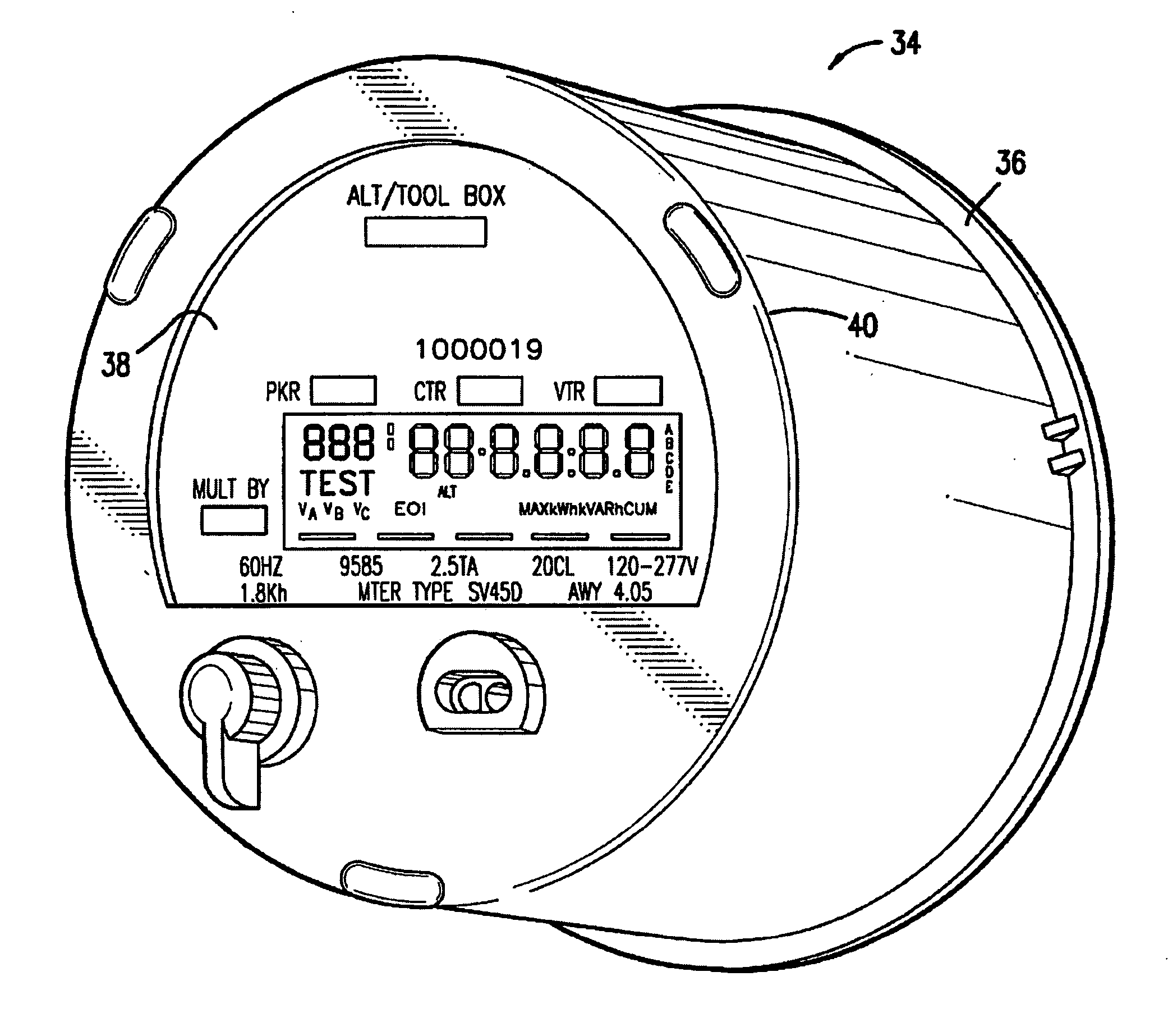
[0055] Referring to FIG. 1, the system of the present invention, generally designated as 20, is an electricity revenue meter that is of the type that is intended to be plugged into a meter socket of the type that is permanently installed at an electricity utility's customer's site. As is well known in the art such sockets are wired into an electric utility's electricity supply lines, and they break the continuity of such supply lines to the customer's premises, so that it is necessary to have a revenue meter installed in such socket for the purpose of restoring such continuity. At the same time such revenue meters meter the usage of electricity by the customer.

[0056] Generally, the sockets are permanently installed at the customer's site at the time the location is constructed or when electric service is to be brought to an existing structure. Thereafter, a revenue meter is installed, and typically “sealed” to the socket to make such installation substantially permanent, except tha...


PUM


Abstract

An integral electronic revenue meter system diagnostics package including a microprocessor, storage memory, preselect series of system diagnostic tests, and recording any results which exceed predefined programmable thresholds, and display means for displaying error and / or diagnostic messages identifying selected diagnostic data and / or errors discovered in the meter tests during a predefined period is included as part of an electricity revenue meter of the type used for collecting metering data for a utility which uses such data for billing purposes. The system automatically senses the type of electrical service in which the revenue meter is installed when the revenue meter is installed in a socket at the customer's premises.

Description

CROSS-REFERENCE TO RELATED APPLICATIONS [0001] This application is a divisional of U.S. Ser. No. 10 / 386,811, filed Mar. 10, 2003, which is a continuation of U.S. Ser. No. 10 / 165,568 filed Jun. 7, 2002, which is a continuation of U.S. Ser. No. 08 / 859,597 filed May 19, 1997, which is a continuation of U.S. Ser. No. 08 / 509,367 filed Jul. 31, 1995 which issued as U.S. Pat. No. 5,631,554 on May 20, 1997. [0002] U.S. Pat. No. 5,631,554 is a continuation-in-part of U.S. Ser. No. 08 / 037,938 filed Mar. 26, 1993 which issued as U.S. Pat. No. 5,469,049 on Nov. 21, 1995; and [0003] U.S. Pat. No. 5,469,049 is related to U.S. Ser. No. 08 / 333,660 filed Nov. 3, 1994 as a divisional of U.S. Ser. No. 08 / 037,938, U.S. Ser. No. 08 / 333,660 issuing Nov. 28, 1995 as U.S. Pat. No. 5,471,137. [0004] Each of the preceding applications and patents are incorporated fully herein by reference.TECHNICAL FIELD [0005] The present invention relates to an integral method and apparatus for conducting system installati...

Claims


Application Information

Patent Timeline
IPC IPC(8): G01R21/133G01R22/00G01R35/04
CPCG01D3/08G01D4/002G01D18/00G01R21/133G01R21/1331Y04S20/32G01R22/00G01R22/10G01R35/04G06Q50/06Y02B90/241G01R21/1335Y04S20/30Y02B90/20
Inventor BRIESE, FORREST WAYNEHYDER, CHARLES CRAIGSCHLARB, JOHN MURRAYLOWE, COY STEPHENFOUQUET, CHRISTOPHE JEAN ANDRE
Owner ITRON
Learn More