
Additive dispensing fluid filter

a technology of additives and fluid filters, applied in the field of liquid filters, can solve the problems of reducing the effect of additives, metal components of water-cooled internal combustion engines are exposed to corrosion and damage, and systems carrying liquids are very often attacked

Inactive Publication Date: 2005-09-08
MANN HUMMEL GMBH
View PDF8 Cites 126 Cited by
  • Summary
  • Abstract
  • Description
  • Claims
  • Application Information

AI Technical Summary

Benefits of technology

[0007] It is an object of the present invention to provide an improved liquid filter which can dispense an additive into a liquid being filtered.
[0008] Another object of the invention is to provide a liquid filter which can dispense an additive into a liquid being filtered and which does not require special safety precautions to be taken during handling.
[0009] It is also an object of the invention to provide a liquid filter which can dispense an additive into a liquid being filtered and which includes a barrier to prevent a person handling the filter prior to its installation from coming into contact with the additive.

Problems solved by technology

Components of systems that carry liquids are very often exposed to attack by the aggressive components of the liquid or to corrosion due to the liquid being carried.
For example, the metal components of water-cooled internal combustion engines are exposed to corrosion and also to damage due to freezing of the cooling water.
However, the effect of such additives declines over a period of time and depends on the conditions to which they are subjected.
The disadvantage of this known liquid filter with integrated inhibitors is that increased safety measures are required for handling this filter until it is used (i.e., from the time the filters are manufactured until the filters are used by a mechanic).
Inhibitors of this type usually have a toxic effect when they come in contact with skin or when inhaled, which is why gloves and a face mask must be worn when handling them.
Consequently, dust or fragments of the toxic inhibitors may fall out when the filters are handled, which is why protective measures are required to be taken in handling the filters.
Another disadvantage of the known arrangement is that the inhibitor in such filters cannot be introduced in liquid or gelatinous form into the filter, because the liquid or gel could flow out when handling the filters.

Method used


Image

  • Additive dispensing fluid filter
  • Additive dispensing fluid filter

Examples


Embodiment Construction

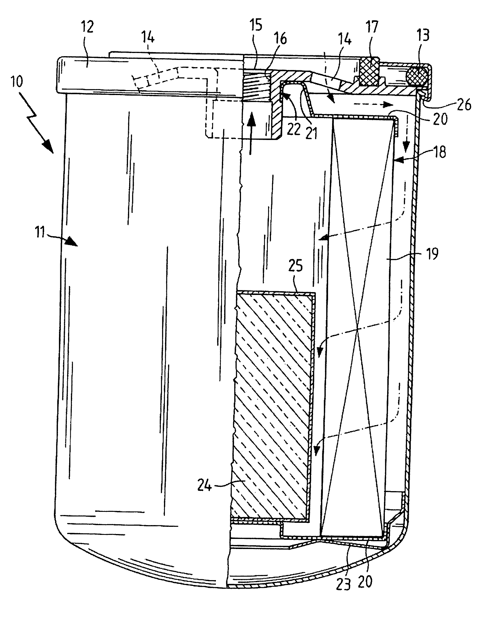
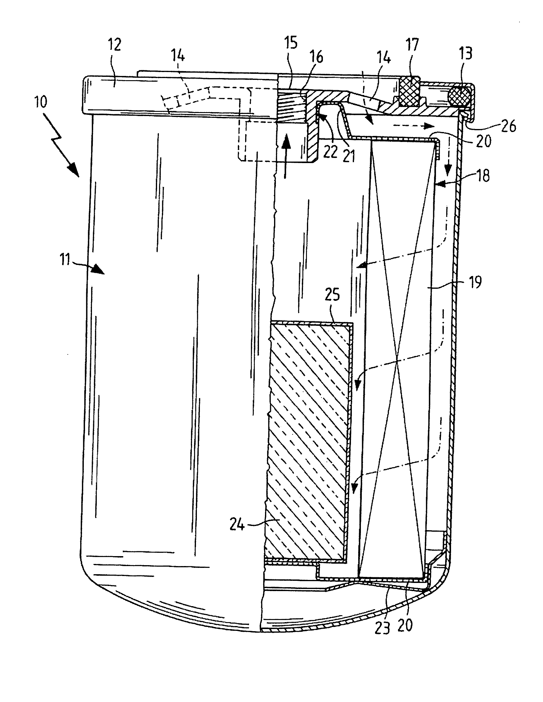
[0028] The figure shows a partially sectional schematic view of a filter cartridge according to the invention. The illustrated liquid filter 10 comprises a housing 11, which is sealed by a cover 12. A gasket 13 is provided in the area of contact between the cylindrical cover 12 and the cylindrical housing 11, with the cover 12 and the housing 11 being joined together by a crimped flanged edge 26. The cover 12 has a plurality of inlet openings 14, each preferably being designed to be circular and arranged in concentric rings.

[0029] It is optionally possible to equip all outlet openings 14 with a one-piece return-flow barrier composed, for example, of silicone rubber. A back-flow barrier of this type may be necessary in certain installation situations. An outlet opening 15 having an inside thread 16 is provided in the center of the cover 12. This liquid filter 10, which is a replaceable filter, is screwed onto the liquid system via the inside thread 16. In order to seal the connectio...


PUM

PropertyMeasurementUnit
liquid-solubleaaaaaaaaaa
thicknessaaaaaaaaaa
solubleaaaaaaaaaa

Abstract

A filter for filtering a liquid, such as coolant for an internal combustion engine, having a filter housing with at least one liquid inlet and at least one liquid outlet, a filter element which is arranged in a sealing manner between the inlet and outlet so that the filter element separates a filtered liquid side from an unfiltered liquid side, and having an additive or inhibitor disposed in the housing such that when contacted by liquid passing through the filter, the additive is released into the liquid, in which the additive is tightly encased in a liquid-soluble material which dissolves on coming in contact with the liquid being filtered.

Description

CROSS REFERENCE TO RELATED APPLICATIONS [0001] This application claims priority from Federal Republic of Germany patent application no. DE 103 55 403.3, filed Nov. 25, 2003, the entire disclosure of which is incorporated herein by reference. BACKGROUND OF THE INVENTION [0002] The present invention relates to a liquid filter for filtering a liquid comprising a filter housing with a liquid inlet and a liquid outlet, a filter element arranged in a sealing manner between the inlet and outlet, and an active agent arranged in the housing for release into a liquid being filtered. The present invention additionally relates to a method for filtering a liquid with simultaneous addition of an active ingredient into the liquid being filtered. [0003] Components of systems that carry liquids are very often exposed to attack by the aggressive components of the liquid or to corrosion due to the liquid being carried. For example, the metal components of water-cooled internal combustion engines are e...

Claims


Application Information

Patent Timeline
Patent Type & Authority Applications(United States)
IPC IPC(8): B01D27/08B01D37/02C10M175/00
CPCB01D27/08B01D2201/34B01D37/025
Inventor NIEMEYER, STEPHANWURSTER, THOMASJUNG, ARMINSCHWARZ, GUENTHER
Owner MANN HUMMEL GMBH
Learn More