Eureka AIR delivers breakthrough ideas for toughest innovation challenges, trusted by R&D personnel around the world.

Vacuum processing apparatus

a vacuum processing and vacuum technology, applied in the direction of transportation and packaging, pressurized chemical processes, coatings, etc., can solve the problems of reducing the efficiency of mounting and dismounting operations, prolonging the operation time, and still has some drawbacks, so as to enhance the operation efficiency of vacuum processing apparatus, facilitate operation, and small installation area

Active Publication Date: 2005-09-08
HITACHI HIGH-TECH CORP
View PDF8 Cites 258 Cited by
  • Summary
  • Abstract
  • Description
  • Claims
  • Application Information

AI Technical Summary

Benefits of technology

[0009] As described above, when a plurality of processing chambers are arranged close to the apparatus, due to guide mechanisms including the movable stages below the apparatus, the size of detachable units becomes large and hence a contact area of the apparatus is enlarged. Accordingly, no consideration has been paid to a point that the number of installable apparatuses on a floor of a clean room or the like on which the apparatuses are installed is lowered so that the manufacturing efficiency when products are manufactured by operating a plurality of apparatuses is lowered.
[0022] Still further, it is also possible to provide the vacuum processing apparatus which can enhance the operation efficiency of the vacuum processing apparatus.

Problems solved by technology

The above-mentioned related prior art, however, has failed to pay the sufficient consideration on following points and hence, the related art still has some drawbacks.
Accordingly, the efficiency of mounting and dismounting operation and maintenance operation is lowered, thus leading to the prolongation of the operation time.
Eventually, there has been a drawback that a non-operative period that the apparatus is not operated is prolonged and hence, the operation efficiency of the apparatus is lowered and the manufacturing cost is increased.
That is, in mounting or dismounting the equipment in the processing chambers, no consideration has been take with respect to the constitution which enhances the operation efficiently other than positioning, thus giving rise to a drawback that the operation time is prolonged and hence, the operation efficiency of the apparatus is deteriorated.

Method used


Image

  • Vacuum processing apparatus
  • Vacuum processing apparatus
  • Vacuum processing apparatus

Examples


Embodiment Construction

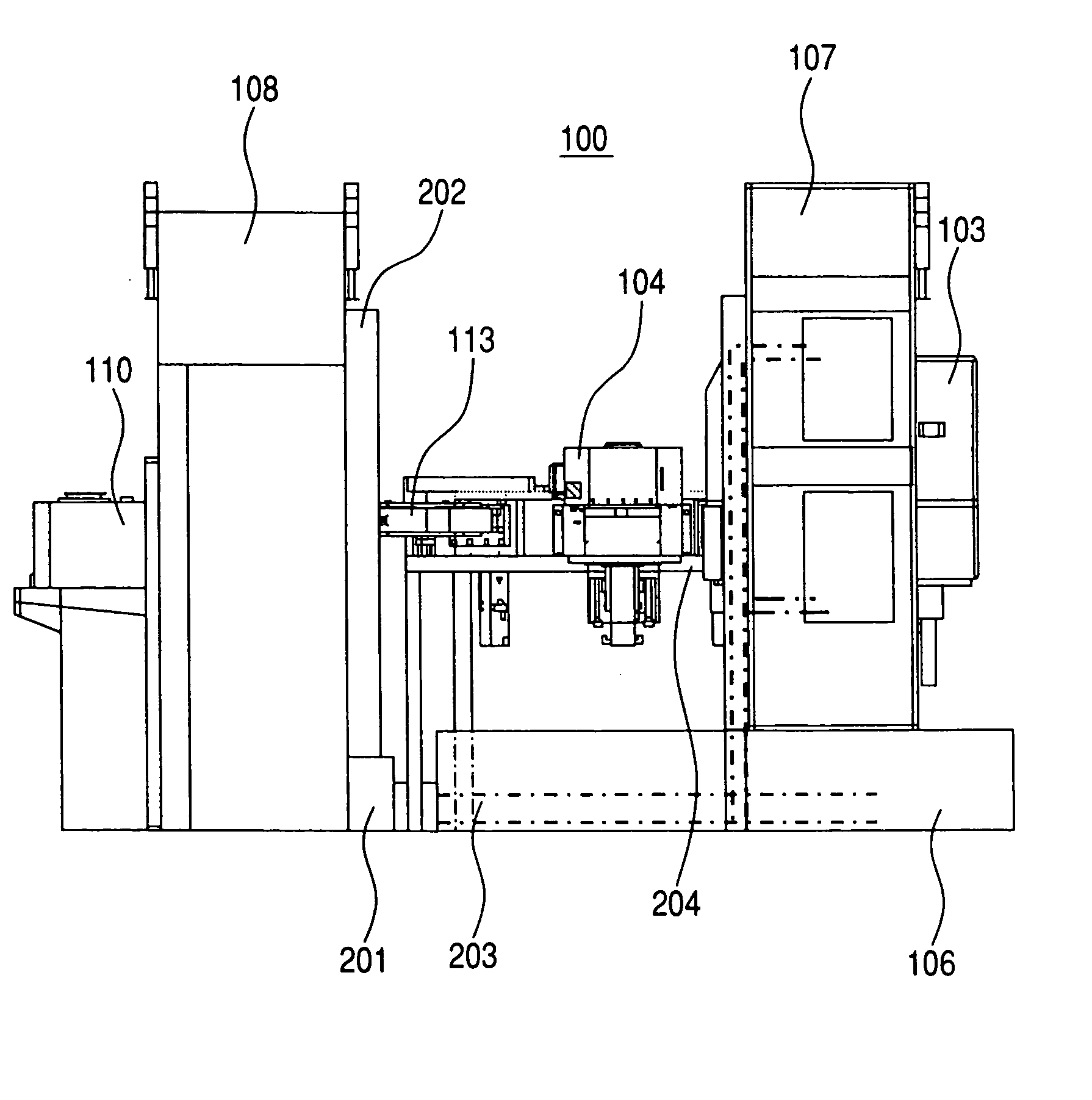
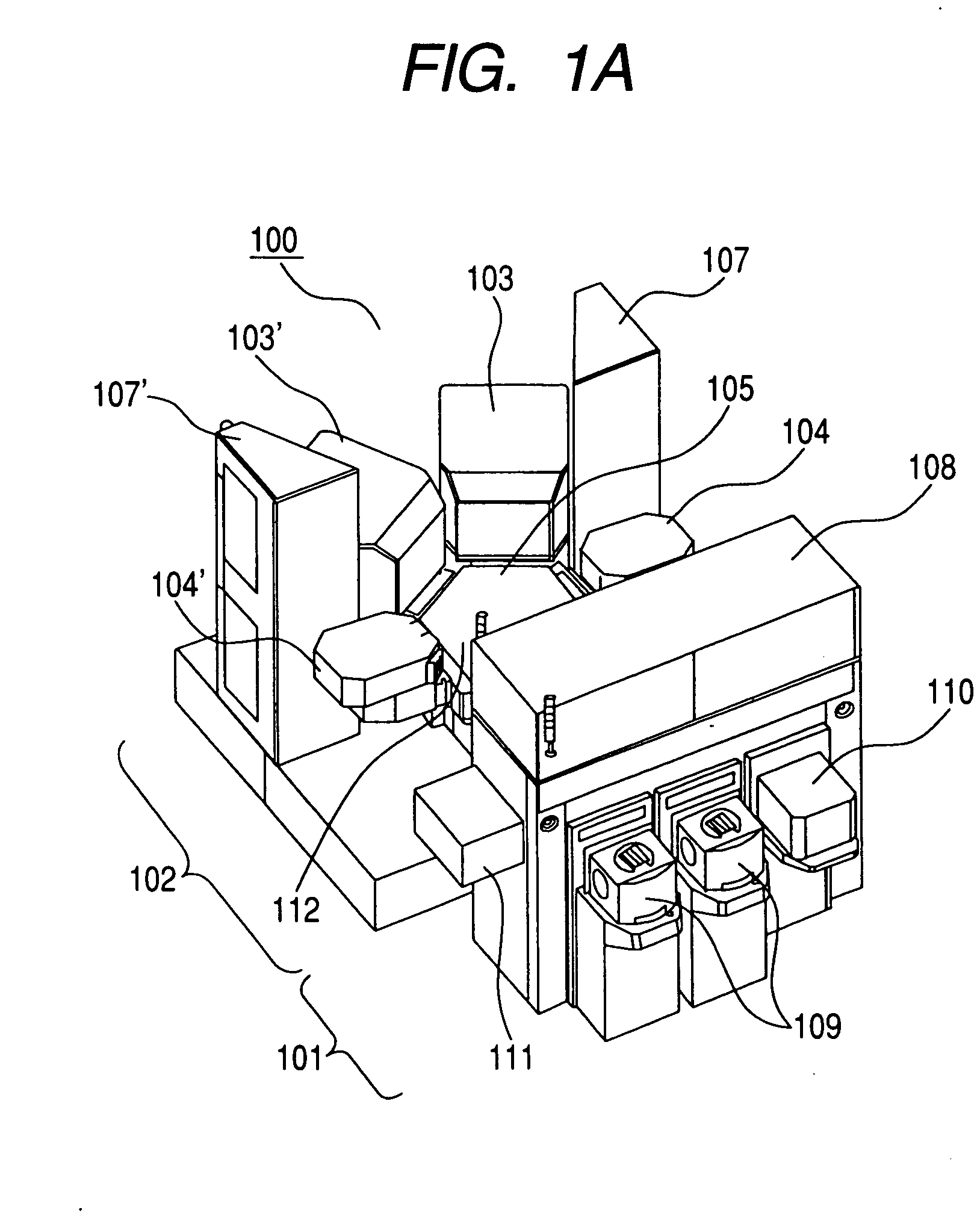
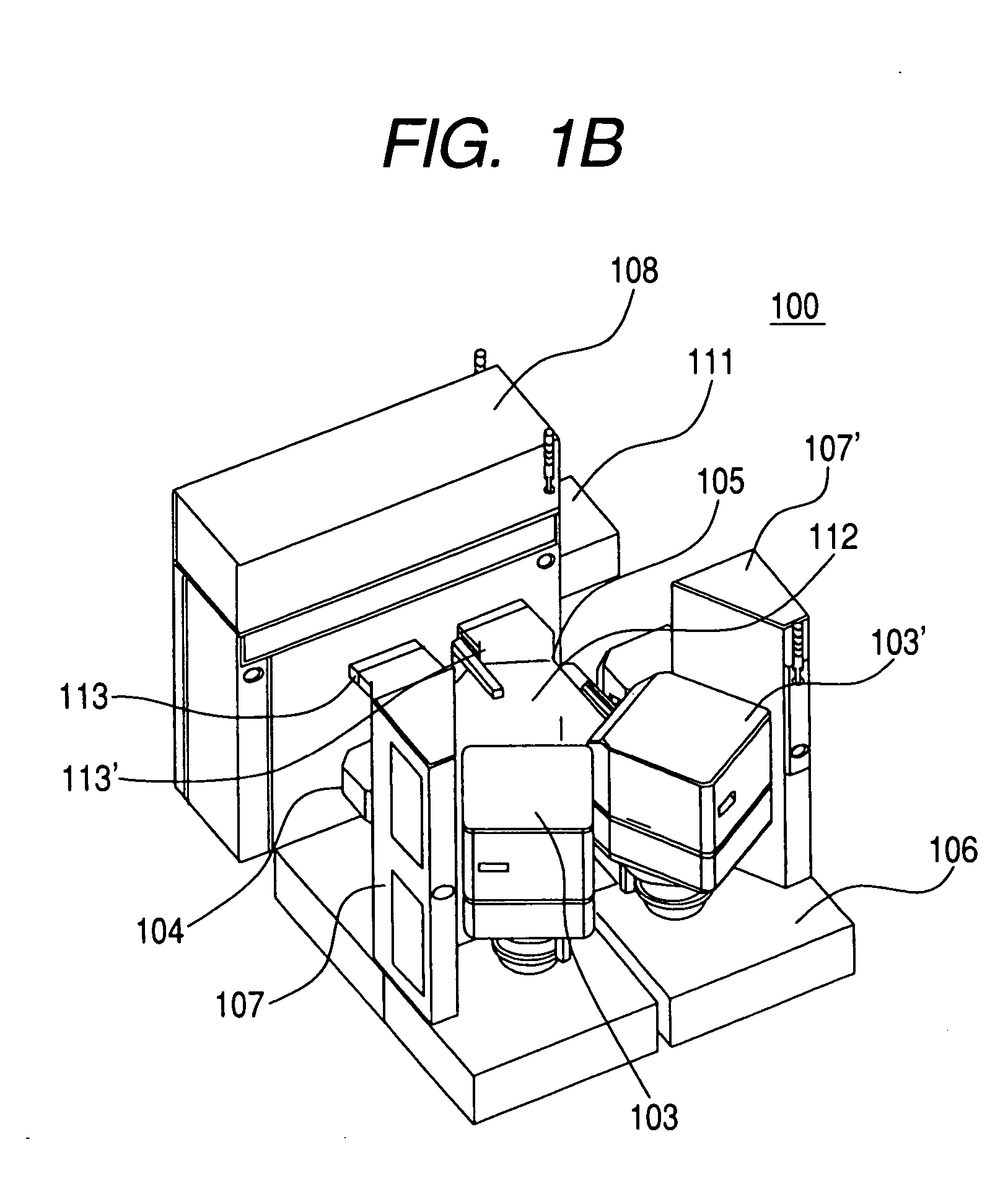
[0045] Preferred embodiments of the present invention are described in detail in conjunction with attached drawings hereinafter. FIGS. 1A and 1B are perspective views showing the whole constitution of a vacuum processing apparatus according to an embodiment of the present invention, in which FIG. 1A is a view as viewed from the front and FIG. 1B is a perspective view as viewed from the back.

[0046] In these drawings, the vacuum processing apparatus 100 of this embodiment is roughly classified into two blocks, that is, front and rear blocks. The front side of an apparatus body 100 constitutes an atmospheric-pressure-side block 101 which enables the transporting of a wafer supplied to the apparatus into a chamber whose pressure is reduced under an atmospheric pressure and the supplying of the wafer into the processing chamber. Behind the apparatus body 100, the process block 102 is arranged. The process block 102 includes processing units 103, 103′ and 104, 104′ which have processing ...


PUM

PropertyMeasurementUnit
Lengthaaaaaaaaaa
Pressureaaaaaaaaaa
Shapeaaaaaaaaaa

Abstract

The present invention provides a vacuum processing apparatus which is small-sized and requires a small installation area. The vacuum processing apparatus includes a vacuum container which has a processing chamber inside thereof, wherein the pressure inside the processing chamber is reduced and plasma used for processing a sample is formed inside the processing chamber, a bed portion which is arranged below the vacuum container and stores a device for supplying electricity and electric signals used for processing inside the vacuum container, and a transport chamber which is connected with the vacuum container and includes a transport device for transporting the sample inside thereof. The vacuum processing apparatus further includes a connector portion which is mounted on the bed portion in a state that the connector portion faces a lower portion of the transport chamber, wherein the bed portion is configured to be detachably mounted on the vacuum processing apparatus in a state that the bed portion performs the connection and the disconnection at the connector portion.

Description

BACKGROUND OF THE INVENTION [0001] The present invention relates to a vacuum processing apparatus which processes an object to be processed in the inside of pressure-reduced apparatus, and more particularly to an apparatus which processes, by using plasma, a semiconductor substrate (wafer) which constitutes the object to be processed in the inside of the apparatus. [0002] In the above-mentioned apparatus, particularly in the apparatus which processes the object to be processed in the inside of the pressure-reduced apparatus, along with a demand for the finer processing and the more accurate processing, there has been a demand for the enhancement of the efficiency of the processing of the substrate which constitutes the object to be processed. Accordingly, in recent years, a multi-chamber apparatus which is provided with a plurality of processing chambers which are connected to one apparatus has been developed, wherein the processing formed of a plurality of steps is applied to a sub...

Claims


Application Information

Patent Timeline
IPC IPC(8): B01J3/00C23C16/00H01L21/02H01L21/3065H01L21/677H01L21/68
CPCH01L21/6719Y10S414/139
Inventor OOHIRABARU, YUUZOUUEDA, AKIRA
Owner HITACHI HIGH-TECH CORP
Why Eureka
Eureka Blog
Learn More