High frequency treatment device having a pair of jaws with electrodes
a treatment device and electrode technology, applied in the field of high frequency treatment devices, can solve the problems of insufficient press to stop blood stanching, difficult to stop projectile bleeding of devices, and requiring relatively complicated surgical procedures in quick and precise manners, and achieve the effect of high frequency and convenient use for both gripping and pressing operations
- Summary
- Abstract
- Description
- Claims
- Application Information
AI Technical Summary
Benefits of technology
Problems solved by technology
Method used
Image
Examples
first embodiment
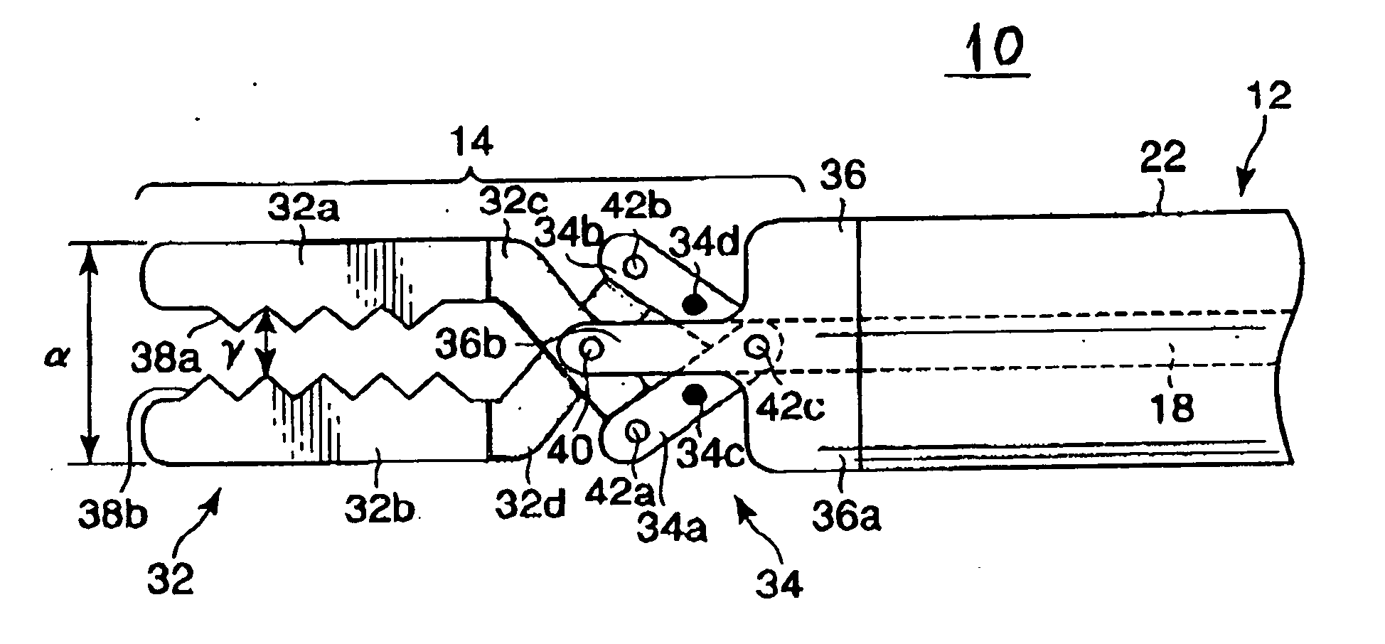
[0057] Referring to FIGS. 1-8, a first embodiment of a high frequency (radio-frequency) treatment device (also called diathermy treatment device) according to the present invention will now be described.
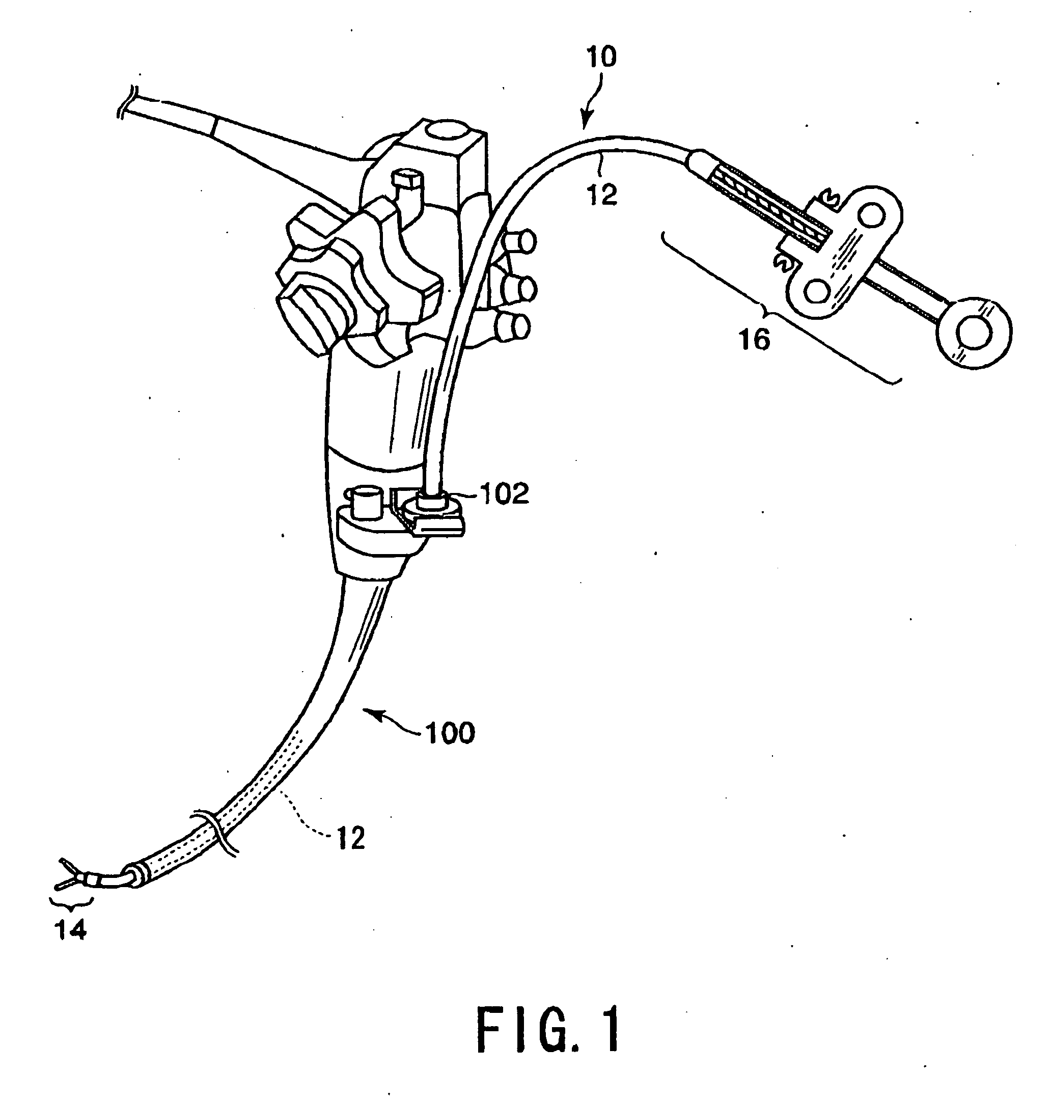
[0058] As shown in FIG. 1, a bipolar forceps (bipolar diathermy forceps) 10 (serving as a high frequency treatment device) according to the present embodiment is provided for cutting open and coagulating a portion of tissue of an object to be treated. This bipolar forceps 10 are used with, for example, an endoscope 100, with the forceps 10 inserted through an insertion channel of the endoscope 100.
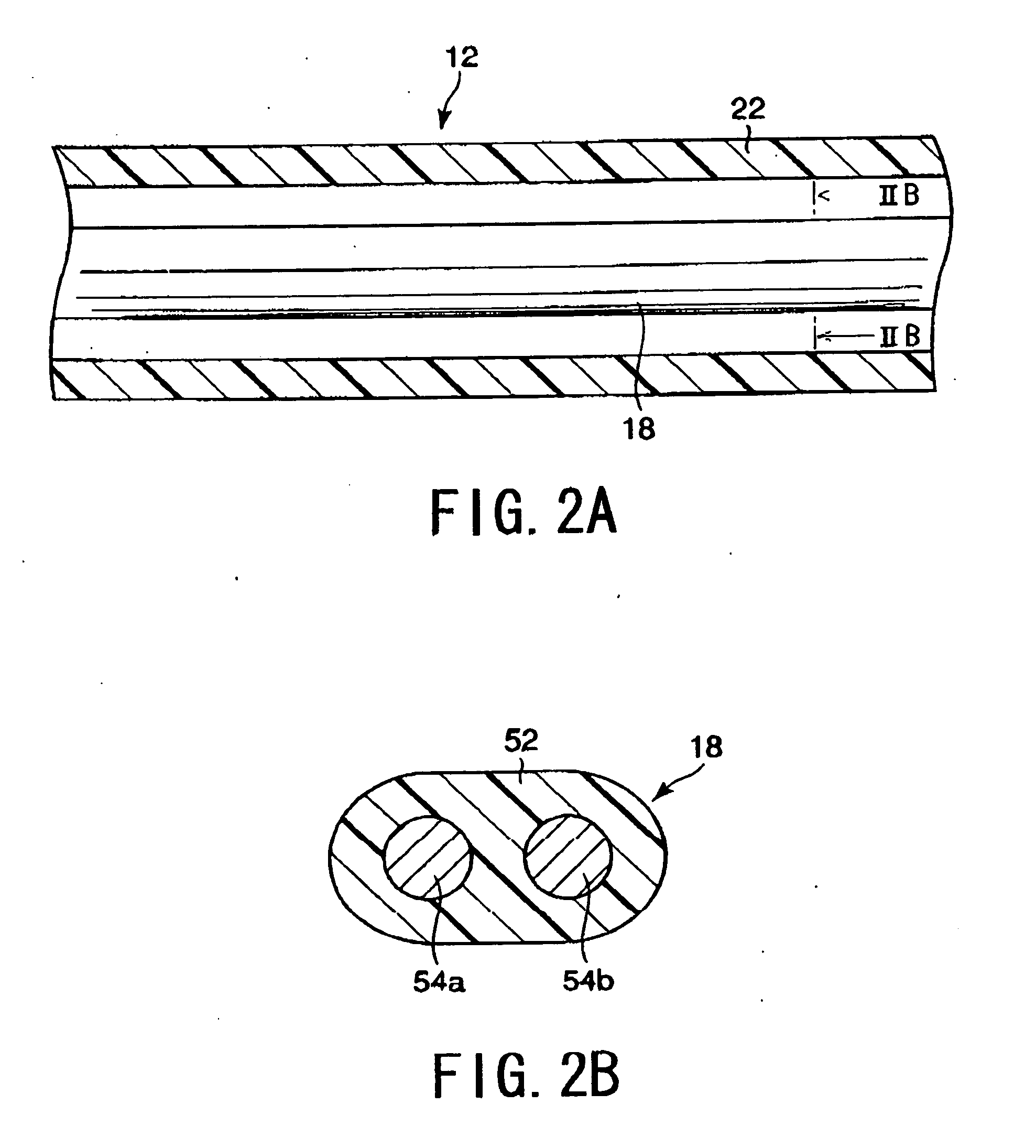
[0059] The bipolar forceps 10 are equipped with a flexible insertion member 12 formed into a thin and long tubular shape whose both ends are respectively referred to as a tip and a base, a treatment member 14 rigidly secured to the tip of the insertion member 12, and a handle 16 formed at the base of the insertion member 12 and configured to operate the treatment member 14.
[0060] As show...
second embodiment
[0094] Referring to FIGS. 9A and 9B, a second embodiment of the high frequency treatment device according to the present invention will now be described. Incidentally, for the sake of simplified explanations, the similar or identical parts in the present and subsequent embodiments to those in the first embodiment will have the same reference numerals.
[0095] The second embodiment corresponds to a modification of the bipolar forces 10 explained in the first embodiment. To be specific, there is provided another example of sustaining the minimum gap γ between the jaws 32a and 32b (precisely, between the gripping surfaces 38a and 38b) when the jaws 32a and 32b are closed. The bipolar forceps 10 according to the present embodiment has a link mechanism 34 different in structures from that explained in the first embodiment.
[0096] As shown in FIG. 9A, the tip of the wire 18 is divided into two so as to connect to first and second branch wires 18a and 18b which are conductive. The first bra...
third embodiment
[0104] Referring to FIGS. 10A and 10B to 13, a third embodiment of the present embodiment will now be described. This embodiment relates to another structure of the jaws.
[0105] A gripper 32 shown in FIGS. 10A and 10B has a pair of jaws 32a and 32b, which are made from an eclectically insulative material, such as ceramics, of high heat resistance. That is, in the present embodiment, the jaws 32a and 32b cannot be used as electrodes by themselves.
[0106] Instead, as shown in FIGS. 10A and 19B, first and second electrode members 68a and 68b each made from conductive materials are arranged on each of the outer surfaces of the jaws 32a and 32b such that the electrode members are located to have a predetermined distance separation therebetween. That is, the two electrode members 68a and 68b, which are charged with positive and negative polarities, are arranged around each of the jaws 32a and 32b in a spiral and positive / negative-alternate fashion. Both of the electrode members 68a and 68...
PUM
 Abstract
Description
Claims
Application Information
 - R&D
- Intellectual Property
- Life Sciences
- Materials
- Tech Scout
- Unparalleled Data Quality
- Higher Quality Content
- 60% Fewer Hallucinations
Browse by: Latest US Patents, China's latest patents, Technical Efficacy Thesaurus, Application Domain, Technology Topic, Popular Technical Reports.
© 2025 PatSnap. All rights reserved.Legal|Privacy policy|Modern Slavery Act Transparency Statement|Sitemap|About US| Contact US: help@patsnap.com


