
Optical device, method for producing the same and recording and/or reproducing apparatus employing the same

Inactive Publication Date: 2005-08-25
SONY CORP
View PDF7 Cites 0 Cited by
  • Summary
  • Abstract
  • Description
  • Claims
  • Application Information

AI Technical Summary

Benefits of technology

[0013] It is therefore an object of the present invention to provide an optical device designed to suppress eccentricity of an incident light beam from the optical axis.
[0014] It is another object of the present invention to provide a recording and / or reproducing apparatus in which it is possible to suppress variations of the spot diameter of the light beam converged and illuminated on the optical recording layer of the optical disc.
[0015] It is still another object of the present invention to provide an optical device made up of plural lenses that can be accurately position-matched and put together, and a method for producing the device.
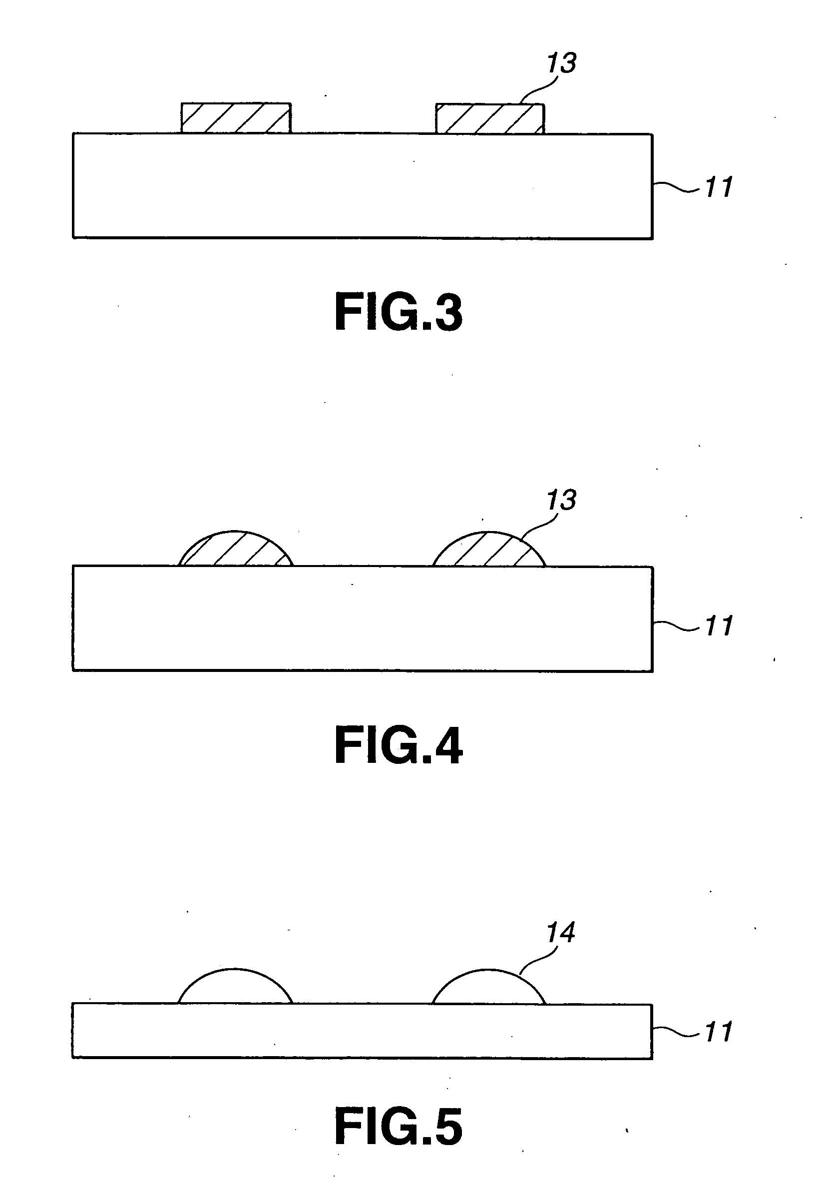
[0016] It is yet another object of the present invention to provide a method for producing an optical device of a small size and a large radius of curvature to a high accuracy.

Problems solved by technology

Meanwhile, if desired to realize a large numerical aperture (NA) by a single lens, a large refracting power is required.
With the molding by the metal molds, it is only possible to mold the lens to a limited degree of precision, whereas, with the position matching based on the outer profile, it is difficult to achieve high precision position matching.
With these lenses, it is unexceptionally difficult to reduce the radius of curvature to render it difficult to produce a small diameter optical lens.
However, it is still difficult with this proposed method to produce a high precision lens.

Method used


Image

  • Optical device, method for producing the same and recording and/or reproducing apparatus employing the same
  • Optical device, method for producing the same and recording and/or reproducing apparatus employing the same
  • Optical device, method for producing the same and recording and/or reproducing apparatus employing the same

Examples


Embodiment Construction

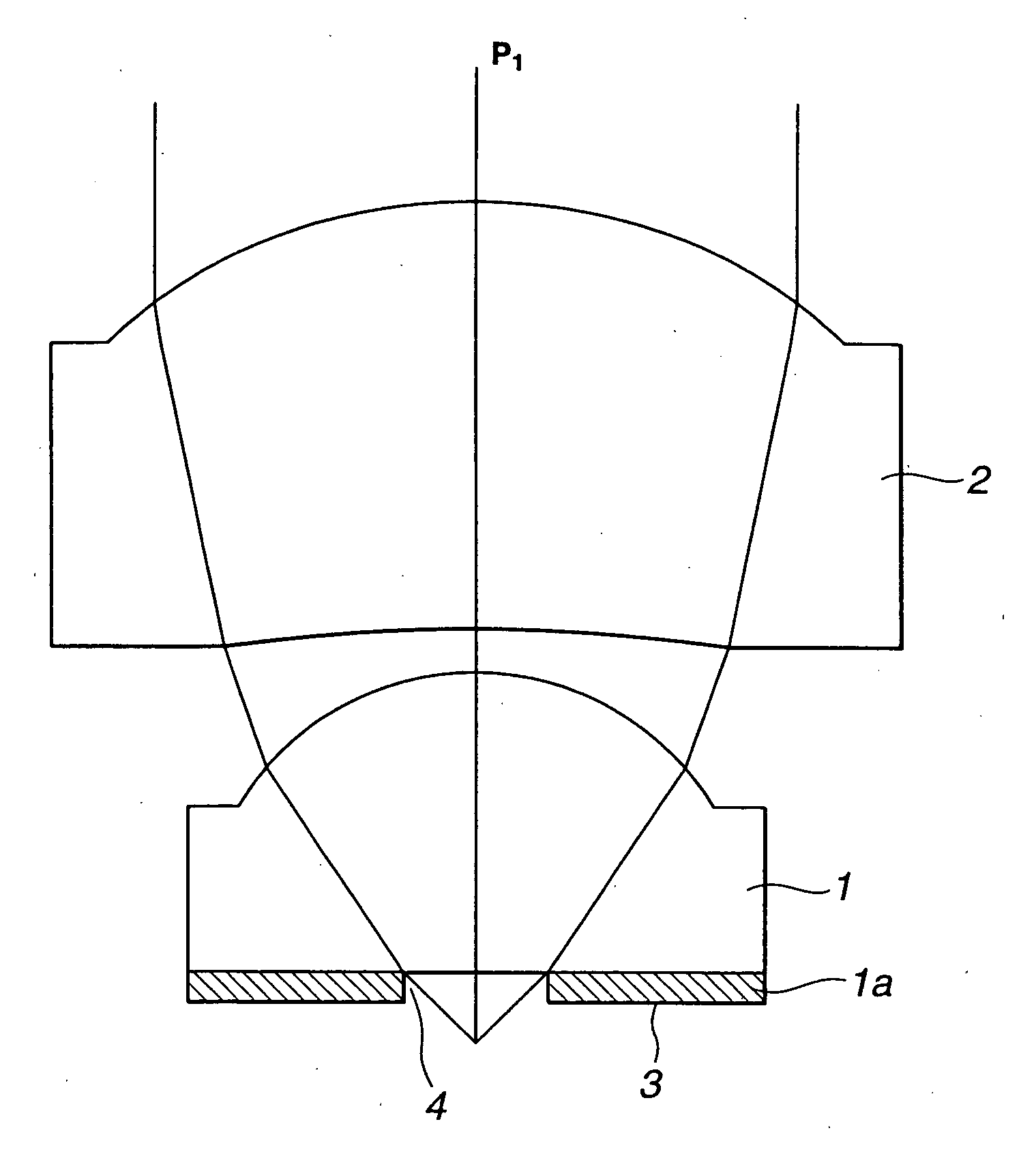
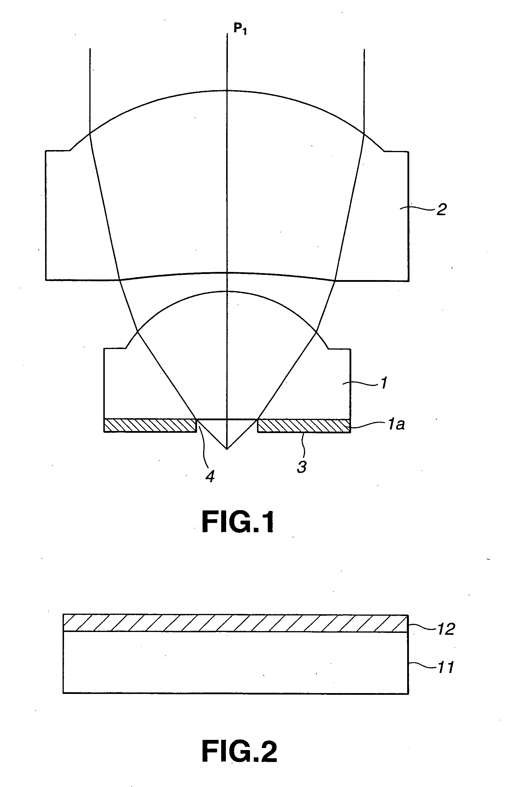
[0035] Referring to the drawings, an optical device, a manufacturing method for the optical device and a recording and / or reproducing apparatus employing the optical device, according to the present invention, are hereinafter explained in detail.

[0036] The optical device according to the present invention is used for an optical pickup for a recording and / or reproducing apparatus employing an optical recording medium, such as an optical disc, and includes a plural number of optical lenses forming means for converging a light beam illuminated on the recording layer of the optical recording medium. The optical device includes a forward lens 1 and a rear lens 2 arranged so that the optical axis thereof coincide with each other, as shown in FIG. 1.

[0037] The forward lens 1 forming the optical device is a so-called hemi-spherical lens having its surface facing the optical recording medium formed as a flat surface 1a carrying a light barrier film 3 operating as light barrier. In the ligh...


PUM


Abstract

An optical device used for converging a light beam on a signal recording surface of an optical disc includes an optical lens for converging the light beam on a signal recording surface of the optical disc and a light barrier portion provided on a surface of the optical lens facing the optical disc. The light barrier portion includes a light transmitting aperture through which is transmitted the light beam converged by the optical lens. The light beam illuminated on the optical disc has its diameter controlled by this light transmitting aperture. The light radiated by a light source so as to be incident to the optical device is converged by the optical lens. The light converged by the optical lens is transmitted through the light transmitting aperture and illuminated on the signal recording surface of the optical disc. The diameter of the light beam illuminated on the signal recording surface of the optical disc is controlled by the light transmitting aperture, and thus the numerical aperture NA of the optical device is determined.

Description

BACKGROUND OF THE INVENTION [0001] 1. Field of the Invention [0002] This invention relates to an optical device which is applied to recording and / or reproducing apparatus for recording and reproducing information signals for a optical recording medium such as optical discs, a method for producing the device, and a recording and / or reproducing apparatus employing the device. [0003] 2. Description of Related Art [0004] There has been proposed an optical disc apparatus in which an optical system is arranged on the side recording layer of an optical disc to achieve high numerical aperture (NA) and hence the high density recording. This optical disc apparatus uses, as an objective lens used in an optical pickup, an optical device having two lenses, such as is shown in Japanese Laying-Open Patent Publication H-10-123410, as light converging means. [0005] Of the two lenses of the optical device, shown in this Publication, the one lying towards the optical disc is a so-called hemi-spherical...

Claims


Application Information

Patent Timeline
IPC IPC(8): G02B13/00G02B5/00G02B9/06G11B7/135
CPCG02B5/005G02B9/06G11B2007/13727G11B7/1381G11B7/139G11B7/1374G02B13/00
Inventor KOUCHIYAMA, AKIRAKISHIMA, KOICHIRO
Owner SONY CORP
Learn More