
Method and device for canceling a land-groove offset component of a focusing error signal in an optical storage system

Inactive Publication Date: 2005-08-25
MEDIATEK INC
View PDF4 Cites 1 Cited by
  • Summary
  • Abstract
  • Description
  • Claims
  • Application Information

AI Technical Summary

Benefits of technology

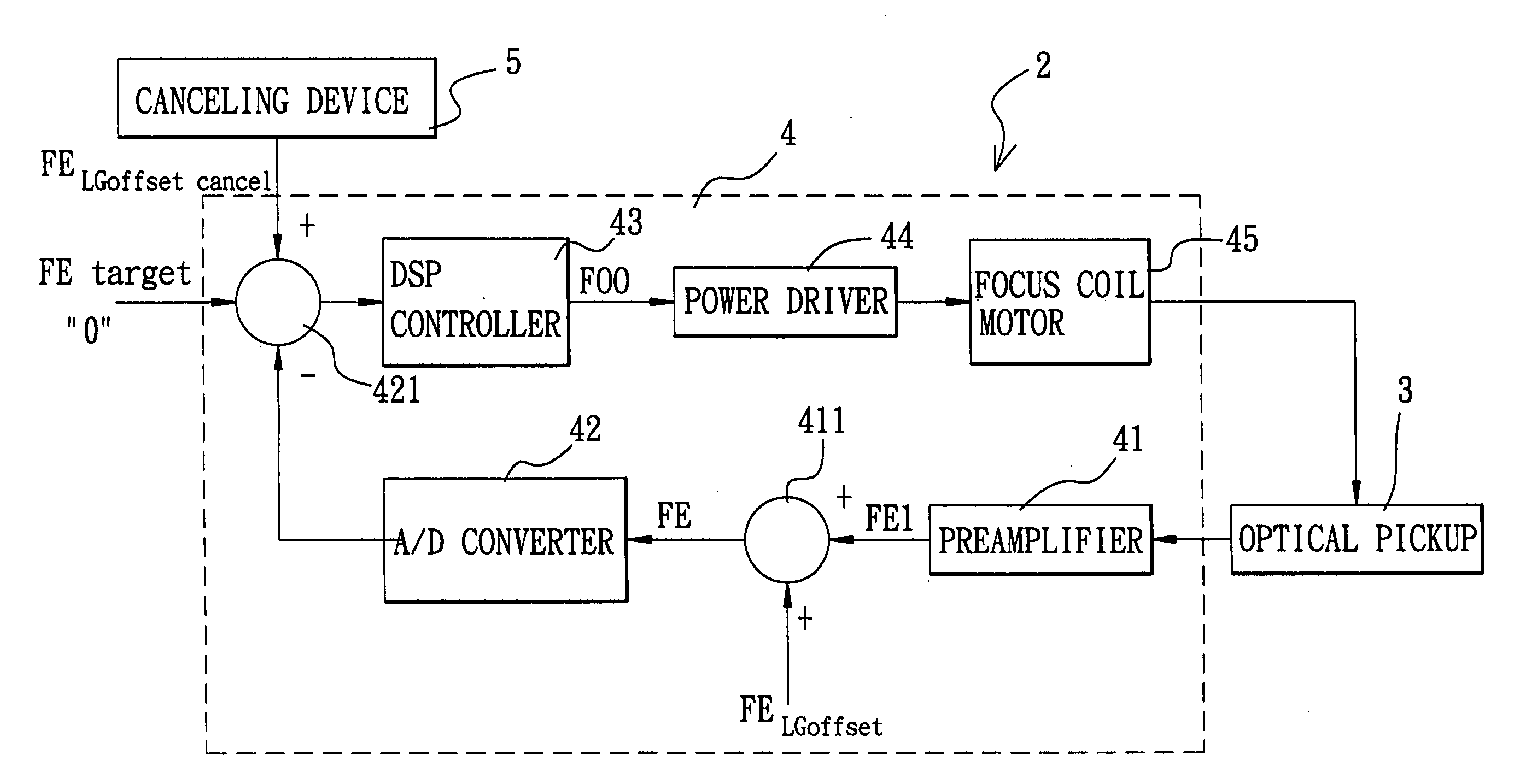
[0013] Therefore, the object of the present invention is to provide a method and apparatus for canceling a land-groove offset compon

Problems solved by technology

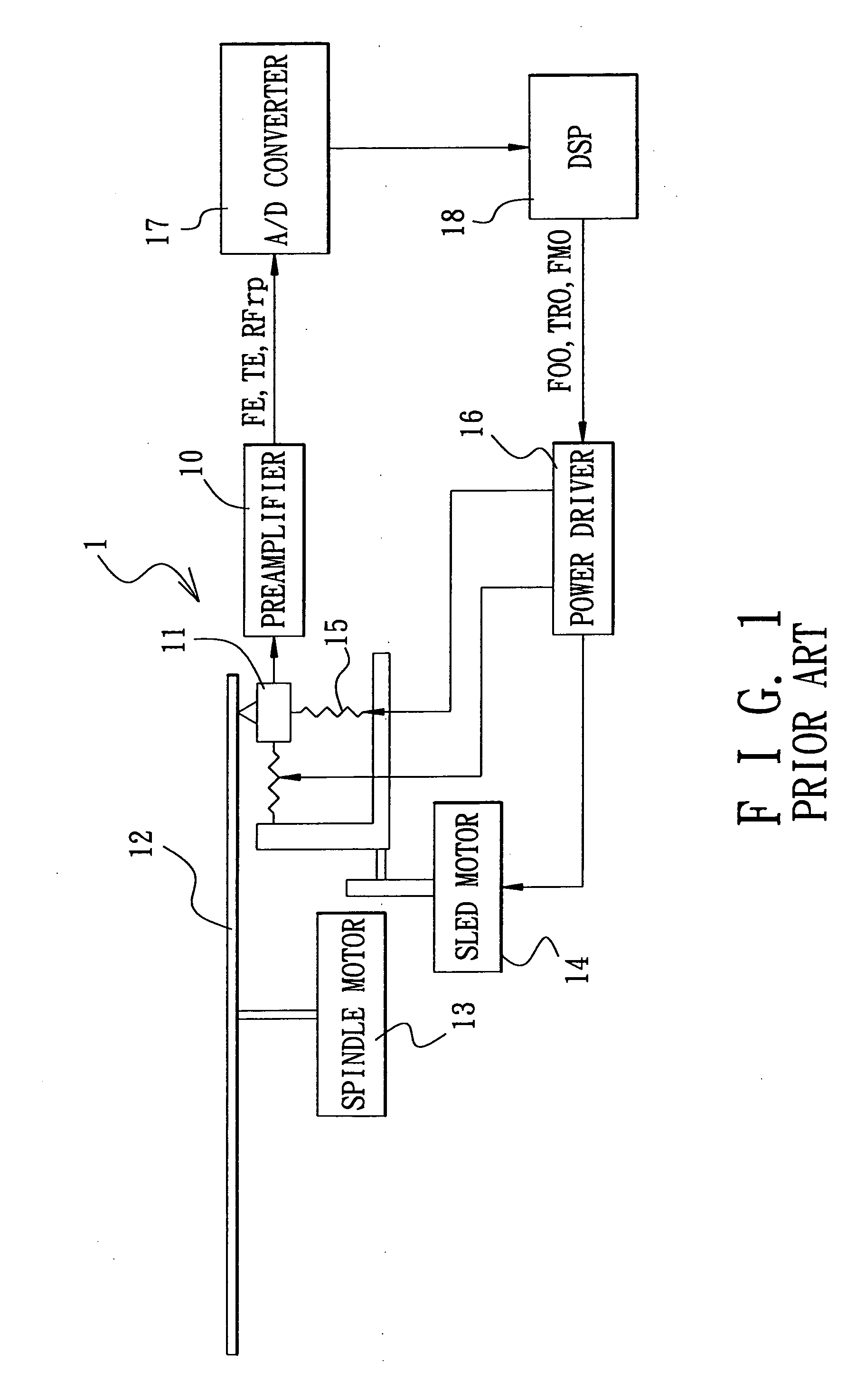
However, since there is actually no problem with the focusing position, the DSP 18 merely generates a series of meaningless control signals for driving the focus coil motor 15 to perform unnecessary adjustments, which not only does not yield any beneficial effect, but also results in waste of energy and harmful heat.
The increase in the amplitude of the focusing control signal (FOO) can result in saturation and subsequent lock-off condition of the servo loop, which affects the stability of focusing control during track seeking and limits the allowable frequency bandwidth for focusing control.
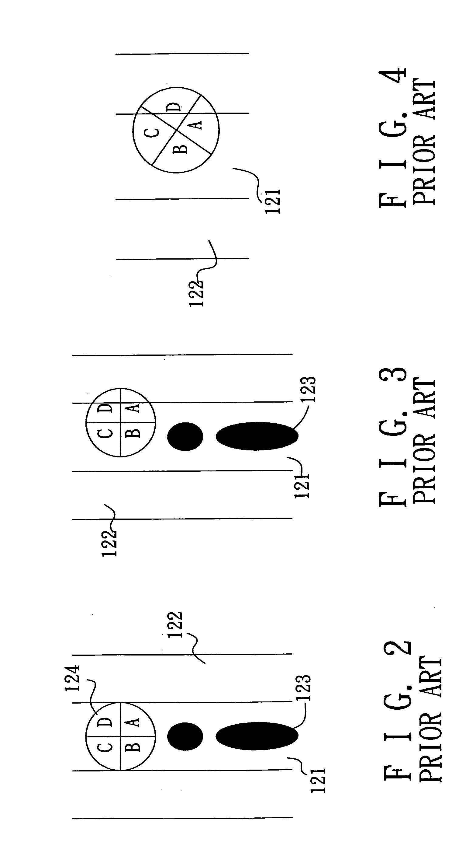
On the other hand, for long periods of track seeking operations, since large land-groove offset components are pres

Method used


Image

  • Method and device for canceling a land-groove offset component of a focusing error signal in an optical storage system
  • Method and device for canceling a land-groove offset component of a focusing error signal in an optical storage system
  • Method and device for canceling a land-groove offset component of a focusing error signal in an optical storage system

Examples


Embodiment Construction

[0031] Since the radio (or wobble) frequency ripple signal (Rfrp) has approximately a 90-degree phase difference with the tracking error signal (TE), it is assumed herein that: (1) the tracking error signal (TE) can be represented by a cosine signal (as in Equation 1) ; and (2) the radio frequency ripple signal (Rfrp) can be represented by a sine signal (as in Equation 2).

TE=cos(ωt)   Equation 1

Rfrp=sin(ωt)   Equation 2

[0032] In FIG. 5, since the focusing error signal (FE) and the tracking error signal (TE) have the same frequency but with a phase difference therebetween during track crossing, the land-groove offset component (FELGoffset) of the focusing error signal (FE) can be determined as follows: FELgoffset=A×FE,where⁢ ⁢A⁢ ⁢is⁢ ⁢a⁢ ⁢constant⁢⁢ =A×sin⁡(ω⁢ ⁢t+Φ),where⁢ ⁢Φ⁢ ⁢is⁢ ⁢the⁢ ⁢phase⁢⁢ ⁢difference⁢ ⁢between⁢ ⁢FE⁢ ⁢and⁢ ⁢TE⁢⁢ =A×(sin⁢ ⁢ω⁢ ⁢t×cos⁢ ⁢Φ+cos⁢ ⁢ω⁢ ⁢t×sin⁢ ⁢Φ)⁢⁢ =A×(Rfrp×cos⁢ ⁢Φ+TE×sin⁢ ⁢Φ)⁢⁢ =G1×Rfrp+G2×TEEquation⁢ ⁢3

[0033] It is evident from Equation 3 that ...


PUM


Abstract

A device for canceling a land-groove offset component of a focusing error signal in an optical storage system includes first and second circuits, and an adder. The first circuit processes a radio (or wobble) frequency ripple signal to obtain a first processed signal that is multiplied by a first gain value (G1) so as to result in a first signal. The second circuit processes a tracking error signal to obtain a second processed signal that is multiplied by a second gain value (G2) so as to result in a second signal. The adder is coupled to the first and second circuits, and adds the first and second signals to produce a compensative land-groove offset component that is to be fed into a focusing device of the optical storage system so as to enable the focusing device to cancel out the land-groove offset component of the focusing error signal.

Description

CROSS-REFERENCE TO RELATED APPLICATION [0001] This application claims priority of Taiwanese application No. 093104427, filed on Feb. 23, 2004. BACKGROUND OF THE INVENTION [0002] 1. Field of the Invention [0003] The invention relates to correction of a focusing error signal in an optical storage system, more particularly to a method and device for canceling a land-groove offset component of a focusing error signal in an optical storage system. [0004] 2. Description of the Related Art [0005] Referring to FIG. 1, a conventional optical storage system 1 is shown to include an optical pickup 11 for reading data from or recording data into an optical disc 12, a spindle motor 13 for driving rotation of the optical disc 12, a sled motor 14 for driving movement of the optical pickup 11, a focus coil motor 15 associated operably with the optical pickup 11, a preamplifier 10, a power driver 16, an analog-to-digital (A / D) converter 17, and a digital signal processor (DSP) 18. The DSP 18 is oper...

Claims


Application Information

Patent Timeline
IPC IPC(8): G11B7/085
CPCG11B7/08505
Inventor YEH, HSIN-CHUNGHSU, JIN-CHUANLI, YUNG-CHIH
Owner MEDIATEK INC
Learn More