
Maintenance cleaning for membranes

Inactive Publication Date: 2005-08-18
ZENON TECH PARTNERSHIP
View PDF18 Cites 14 Cited by
  • Summary
  • Abstract
  • Description
  • Claims
  • Application Information

AI Technical Summary

Benefits of technology

[0011] An object of the present invention is to provide a method of cleaning filtering membranes with a backwashed liquid cleaner which reduces the rate of decline in the permeability of the membranes so that intensive recovery cleaning is required less frequently.

Problems solved by technology

Over time, the solids foul the membranes which decreases their permeability.
Such back washing and agitation is partially effective in removing solids from the surface of the membranes, but is not very effective for removing solids deposited inside the membrane pores and is almost ineffective for removing any type of solid chemically or biologically attached to the membranes.
Accordingly, fouling continues despite regular back washing and agitation and the permeability of the membranes decreases over time.
After a short time, typically in the range of a couple of weeks, the permeability of the membranes reaches an unacceptable value and a different type of cleaning, which may be referred to as intensive recovery cleaning, is preformed.
Although necessary, intensive recovery cleaning may disrupt permeation for an extended period of time and is harsh on the membranes.
After such intensive recovery cleaning, the permeability of the membranes is partially restored, but the remaining useful life of the membranes will have been reduced.
Such a process avoids removing the membranes or tank water from the tank but the amount of chemical cleaner is large.
For waste water applications, the amount of chemical used in each cleaning event may not destroy the biological processes occurring in the waste water, but it still shocks the microorganisms and disrupts the digestion of mixed liquor.
Significant spikes of pollutants are observed after each cleaning by such methods.
For potable water applications, the amount of chemical cleaner remaining in the tank after such cleaning events makes such methods unusable.
With chemical cleaners based on chlorine, for example, such methods produce unacceptable levels of residual chlorine and trihalomethanes in the permeate.

Method used


Image

  • Maintenance cleaning for membranes
  • Maintenance cleaning for membranes
  • Maintenance cleaning for membranes

Examples


example 1

[0053] Waste Water Treatment

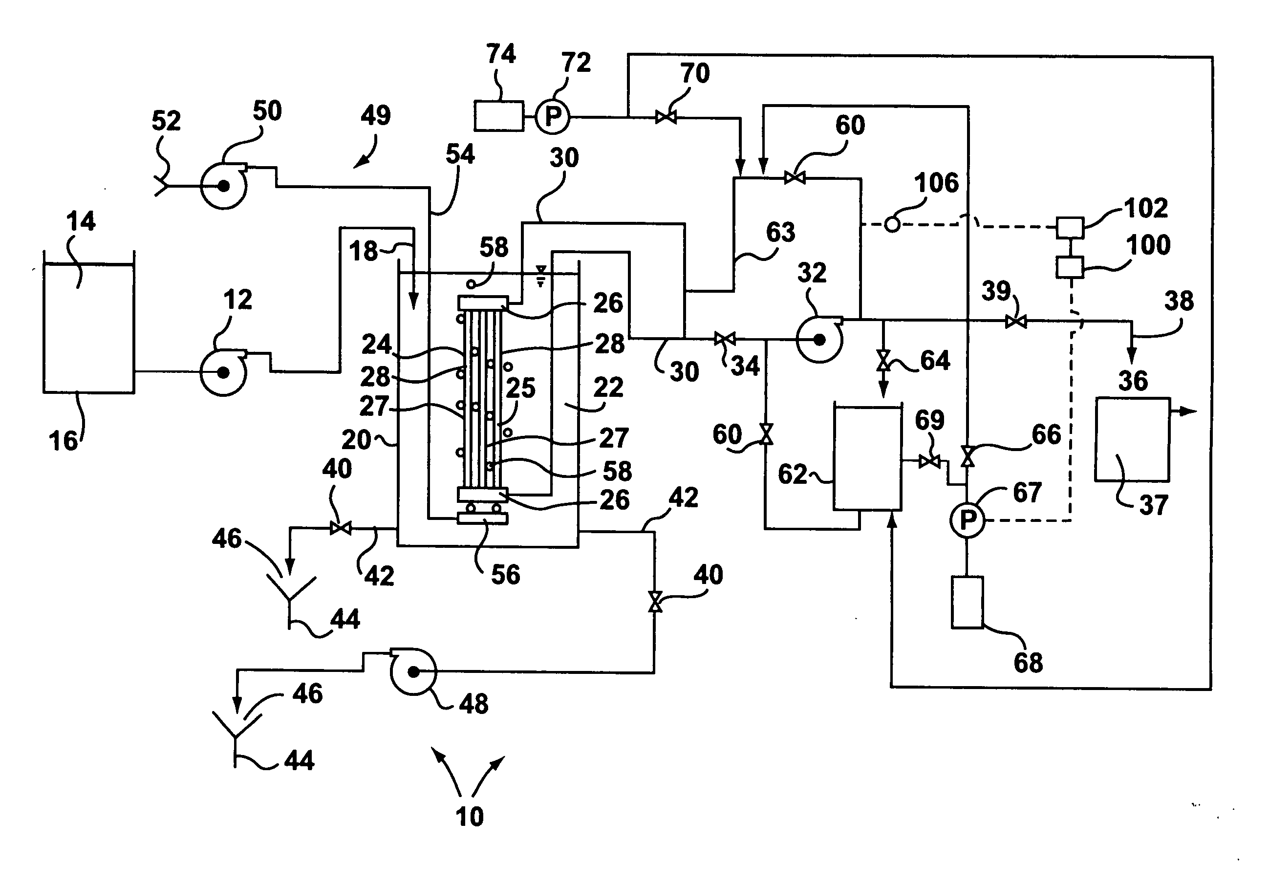
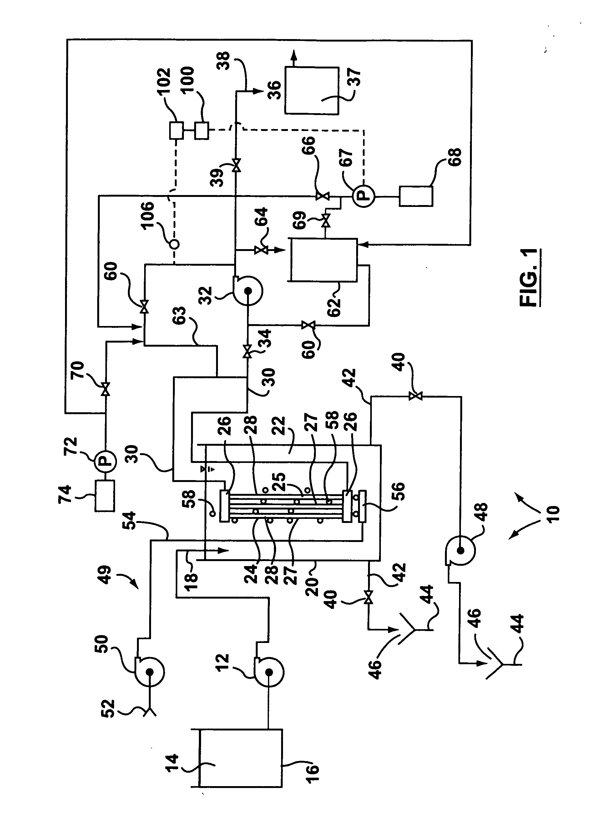
[0054] An experimental membrane bioreactor using a ZEEWEED 500 membrane module having 46 square metres of membrane surface area was built for treating waste water and, in particular, for carbon oxidation, nitrification and phosphorus removal. At all times, the flow rate of permeate through the membranes was maintained at 25.5 / m2 / h and the solids concentration in the bioreactor averaged between 15 g / l and 20 g / l. The average flow through the bioreactor was 1,000 cubic metres per day and the peak flow was 2,000 cubic metres / day.

[0055] The bioreactor was first operated without cleaning according to the invention for 90 days. Permeability was not sustainable and decreased continuously. At the end of this time, permeability of the membranes had dropped to less than 75 L / m2 / h / bar.

[0056] The bioreactor was then operated with a fresh membrane module for 90 days with maintenance cleaning according to the present invention. The cleaning was performed twice per w...

example 2

[0058] Potable Water

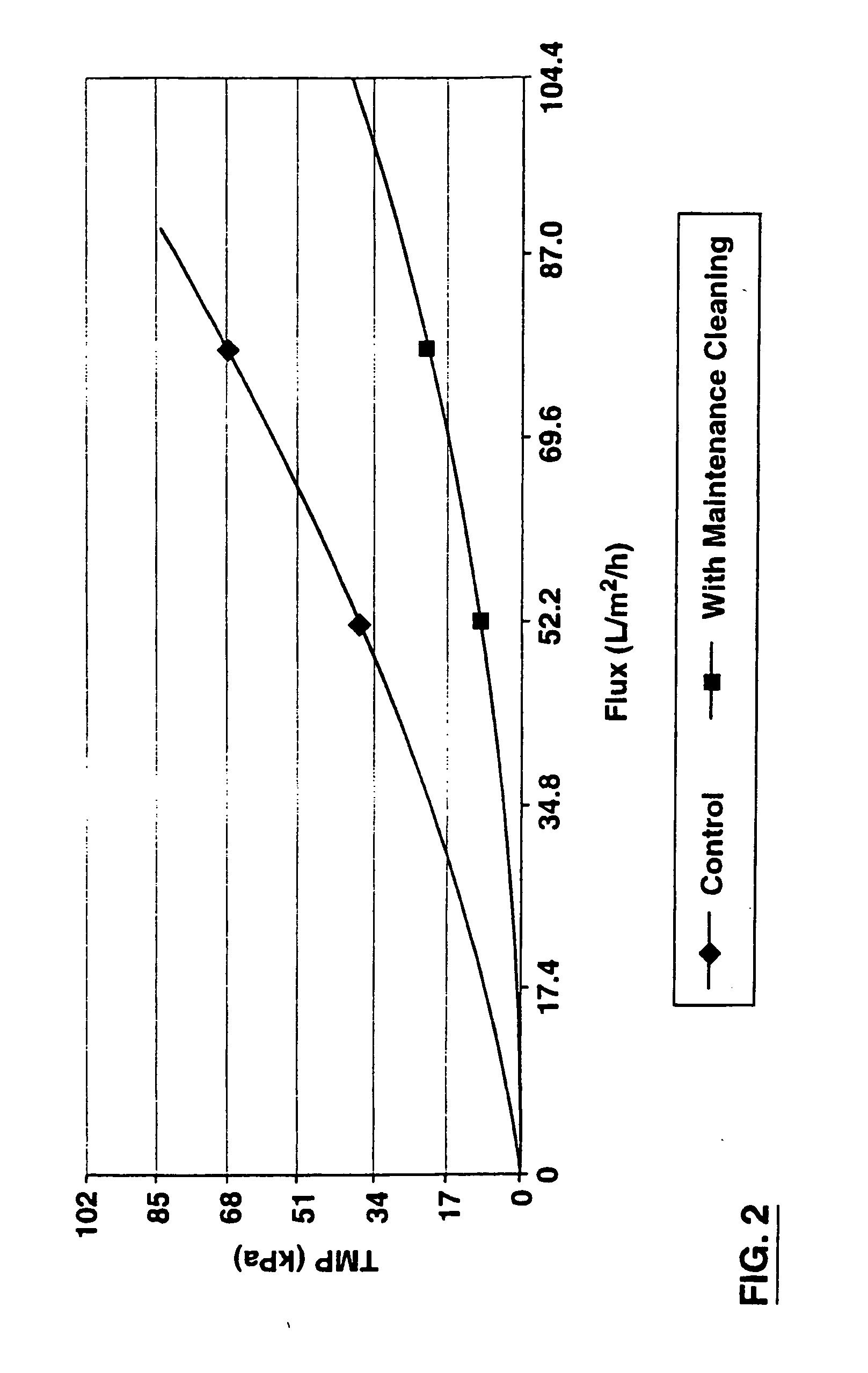
[0059] An experimental membrane bioreactor using ZEEWEED 10 membrane modules having 0.9 square metres of membrane surface area each was built for treating lake water to produce potable water. All experiments were performed at constant flux in which the flow is kept constant and the transmembrane pressure (TMP) was allowed to increase as membranes fouled. The raw water conditions were as follows: [0060] 1 Temperature (C.) 10-20 TOC (mg / l) 3.0-5.0 Turbidity (ntu) 4.0-9.0 Apparent Colour (Pt Co units) 10-50 True Colour (Pt Co units) 5.0-20.0

[0061] Experiments were performed with and without maintenance cleaning and at different fluxes. Cleaning events were done three times per week with 100 mg / l NaOCl for 30 minutes. The cleaning dosage was between 320 and 430 mg NaOCl per square metre of membrane per week.

[0062]FIG. 2 summarises the results obtained with and without maintenance cleaning. Each test lasted about 45-60 days. After an initial increase in TMP, the TM...

example 3

[0064] Heated Water as a Chemical Cleaner

[0065] An experimental membrane bioreactor was built for treating a typical municipal waste water. ZW10 membrane modules were used each having a surface area of 0.9 square metres. The concentration of biomass was between 15 to 20 gMLSS / L, corresponding to a volumetric loading of between 1.2 to 2.3 kg COD / m3 / d. COD and TKN removal were better than 95% with dissolved oxygen residuals between 0.5 and 1.5 mg O2 / L in the tank.

[0066] Experiments were performed at a constant transmembrane pressure of 34 kPa and the permeate flux was allowed to decline as the membranes fouled. Two modules were tested under the same conditions, one with and one without heated water maintenance cleaning. For cleaning, heated water maintenance cleaning was performed with water heated to 40C for 1 hour every day. FIG. 3 shows the net flux results as a function of time and indicates that the heated water maintenance cleaning resulted in an improvement in flux averaging ...


PUM


Abstract

A method of cleaning ultrafiltration or microfiltration membranes reduces the rate of decline in the permeability of the membranes so that intensive recovery cleaning is required less frequently. In one aspect, cleaning events using a chemical cleaner are started before the membranes foul significantly and are repeated between 1 and 7 times per week. The product of the concentration of the chemical cleaner expressed as an equivalent concentration of NaOCl and the duration of all cleaning events is between 2,000 minutes·mg / l and 30,000 minutes·mg / l per week. When performed in situ, each cleaning event comprises (a) stopping permeation and any agitation of the membranes, (b) backwashing the membranes with a chemical cleaner in repeated pulses and (c) resuming agitation, if any, and permeation. The pulses last for between 10 seconds and 100 seconds and there is a time between pulses between 50 seconds and 6 minutes. Each cleaning event typically involves between 5 and 20 pulses. In another aspect, cleaning events using a pulsed backwash of heated water are similarly started before the membranes foul significantly and are repeated between twice a day and once every two days.

Description

[0001] This application is (1) a continuation-in-part of U.S. patent application Ser. No. 10 / 461,687 filed Jun. 16, 2003 which is a continuation of U.S. patent application Ser. No. 09 / 425,234, filed Oct. 25, 1999 which is an application claiming the benefit under 35 USC 119(e) of provisional application No. 60 / 146,154, filed Jul. 30, 1999; (2) a continuation-in-part of U.S. patent application Ser. No. 09 / 916,247 filed Jul. 30, 2001 which is (i) a continuation-in-part of U.S. patent application Ser. No. 09 / 425,234, filed Oct. 25, 1999, (ii) a continuation-in-part of U.S. patent application Ser. No. 09 / 425,235, filed Oct. 25, 1999; and, (iii) continuation-in-part of U.S. patent application Ser. No. 09 / 425,236, filed Oct. 25, 1999; and, this application is (3) a continuation-in-part of U.S. patent application No. U.S. patent application Ser. No. 09 / 425,234, filed Oct. 25, 1999 which is an application claiming the benefit under 35 USC 119(e) of provisional application No. 60 / 146,154, fi...

Claims


Application Information

Patent Timeline
IPC IPC(8): B01D61/18B01D65/02B01D65/06B01D65/08C02F1/44C02F3/12
CPCB01D61/18B01D65/02B01D65/08B01D2321/04B01D2321/08C02F3/1273B01D2321/16B01D2321/185B01D2321/2066C02F1/444B01D2321/12Y02W10/10
Inventor RABIE, HAMID R.HUSAIN, HIDAYATBEHMANN, HENRY
Owner ZENON TECH PARTNERSHIP
Learn More