Display shelving device with integrated electrical power supply means for lighting units
Inactive Publication Date: 2005-08-11
C S FRANCE
View PDF5 Cites 37 Cited by
- Summary
- Abstract
- Description
- Claims
- Application Information
AI Technical Summary
Benefits of technology
[0008] The present invention aims to provide a display shelving device with multiple interlocking strip sections that allows any lighting arrangement designed to highlight articles presented, in particular a “front” lighting system, to be implemented with lighting unit electrical supply means that allow a free choice of the position of the lighting units while providing an extreme ease of use and a satisfactory degree of safety by ensuring a suitable protection of the electrical conductors.
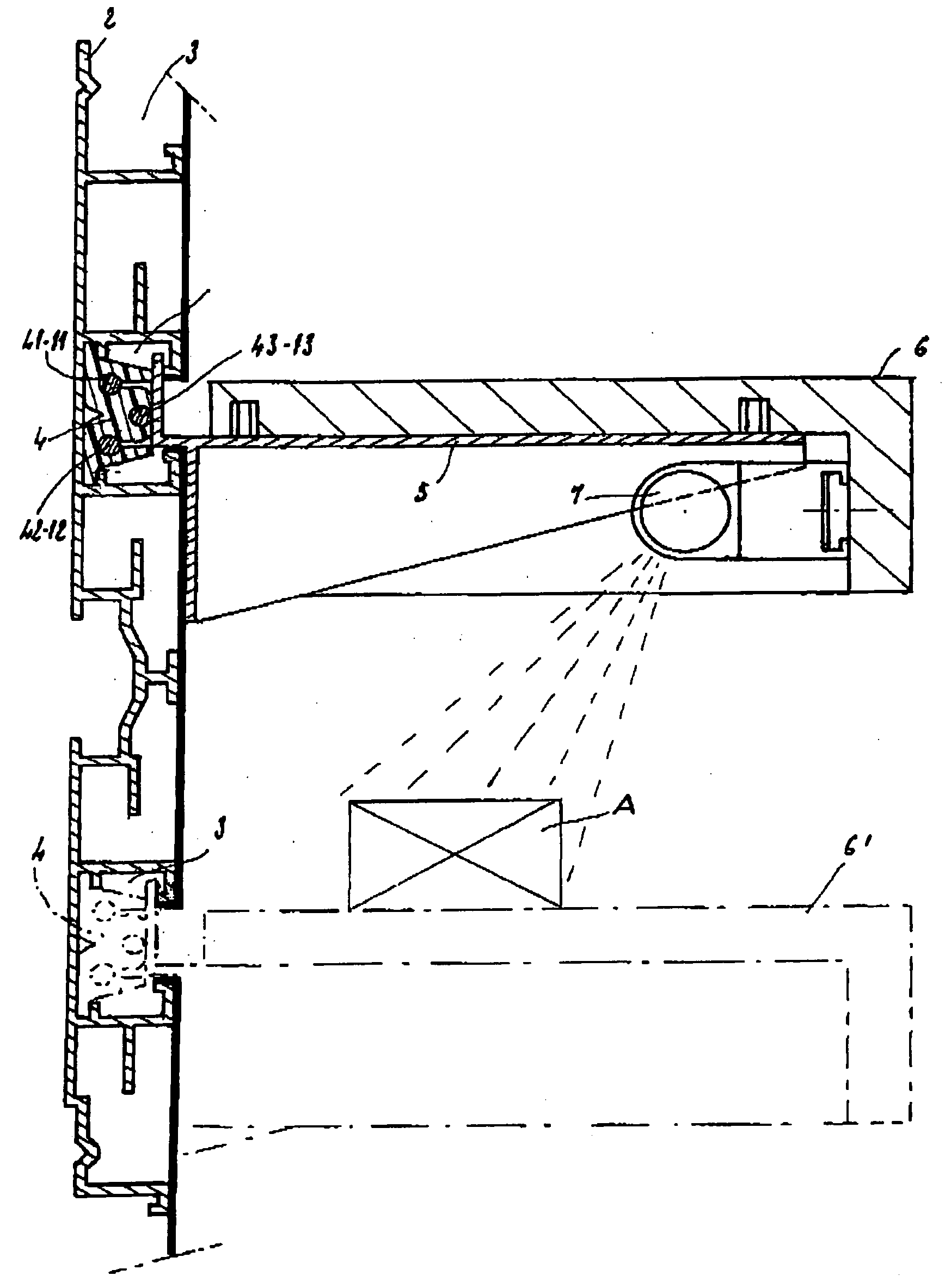
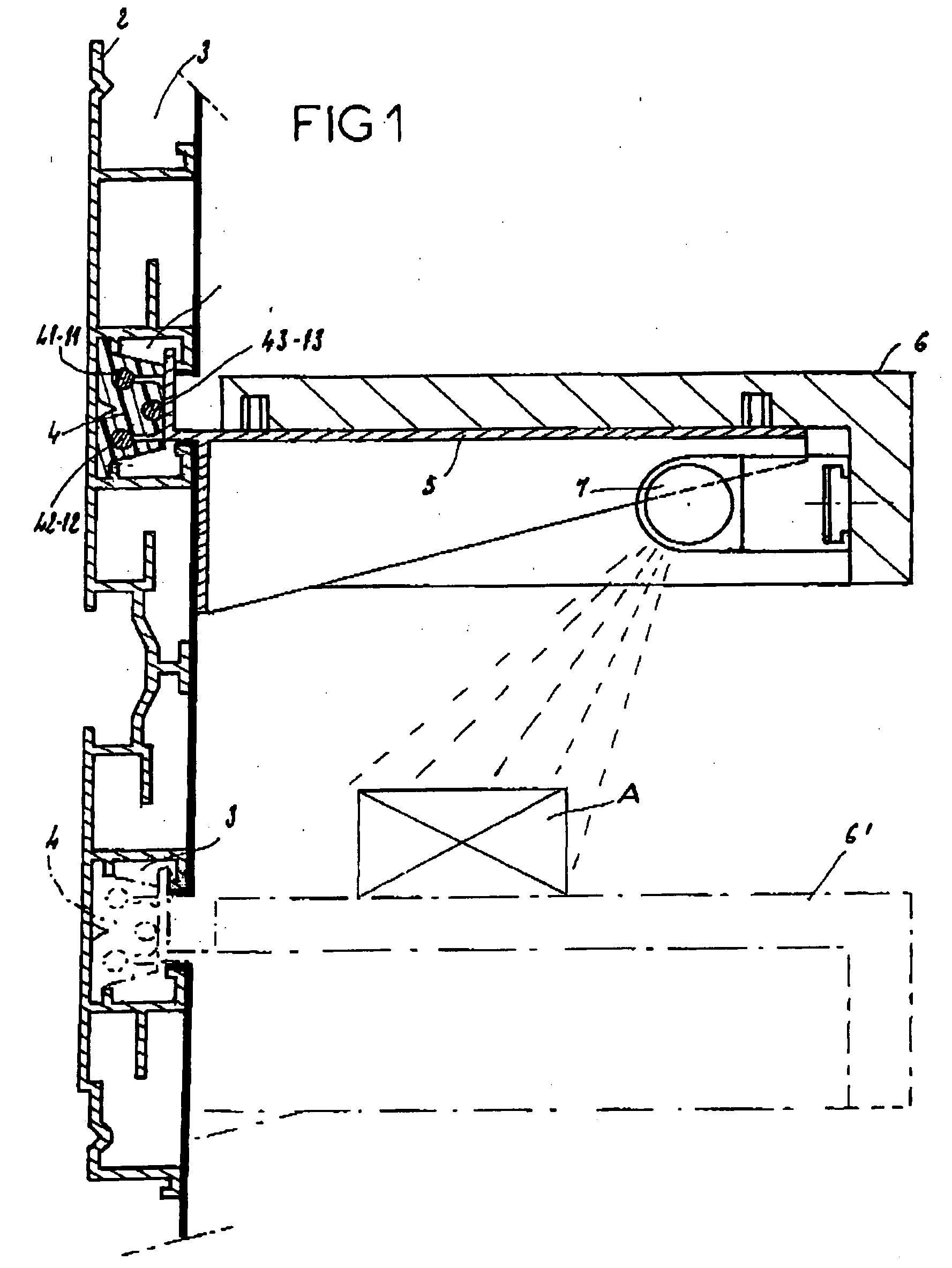
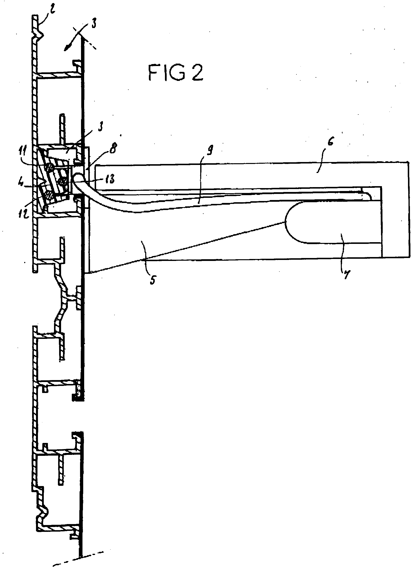
[0010] Accordingly, the inventive idea consists in mounting tray support mechanisms, of the bracket type, in the longitudinal recesses formed in the strip sections and / or at the junction of these sections, such that the lighting can be shifted to any position underneath the trays in order to highlight an article disposed on a lower tray. Moreover, the retention of the support mechanisms and the electrical supply of the lighting unite can be provided in a single and same longitudinal recess. Aside from its esthetic appeal of being discreet, this arrangement ia particularly desirable for equipping retail stores and display premises, since it provides an enhanced ease of use and a greater freedom in the choice of position for the trays. The device obtained is therefore completely modular as regards both the shelf positioning and the lighting.
[0012] This allows the lighting unit to be “suspended” at any position on the tray, even well away from the panel formed by the interlocking sections, for example in order to implement a “front” lighting of the articles to be presented. Each adaptor, of a type known per se, cooperates with the electrical conductors integrated into the strip sections, and is connected to the lighting unit by electrical links such as simple wires. The displacement of an adaptor from one position to another can be easily and rapidly carried out. The adaptor can supply any type of lighting unit (lamp, spotlight, fluorescent tube, etc.).
Problems solved by technology
In such a known system, the power supply electrical conductors are therefore directly accessible and are not protected, which prohibits the system being used with normal mains voltages (i.e. 220 volts in France).
Thus, the use of this system is limited to specific lighting units operating at low voltage.
On the other hand, the system of U.S. Pat. No. 4,747,025 is not at all adapted to the electrical supply of lamps operating at normal voltage.
Moreover, this document does not describe any means allowing articles of various kinds to be put on display.
This known presentation or display device for commercial lighting units satisfies the safety standards by a suitable protection of the electrical conductors, and allows a wide choice of position for the lighting units, but it is only satisfactory when the lighting units themselves constitute the articles on display.
For the display of other types of articles, for which it is desired to enhance the commercial appeal, this device does not allow any desired kind of lighting arrangement, in particular a “front” lighting system, to be used.
Method used
View moreImage
Smart ImageViewing Examples
Examples
Embodiment Construction
[0030] The device described above can, in particular, be used for equipping retail stores and display premises.
[0031] The scope of the invention, as defined in the appended claims, would still be respected by, notably; [0032] producing the trays and their support brackets as a single piece; [0033] using any kind of lighting unit such as a lamp, tube or bulb in any configuration and in any number.
Login to View More PUM
 Abstract
This display shelving device is formed from a panel with multiple interlocking metal strip sections installed and fixed against a plane wall or special supporting structures, and comprising longitudinal recesses in the strip sections and / or at the junction of these sections. Slats made of insulating synthetic material are mounted in the recesses of the strip sections and include longitudinal slots within which power supply electrical conductors run longitudinally. The latter supply lighting units by means of detachable adaptors retained in the recesses, and of electrical links with the lighting units. Support brackets are mounted in the recesses in order to support detachable trays on the underside of which are fixed the lighting units. Application: presentation of articles (A) with lighting on retail or display premises.
Description
BACKGROUND OF THE INVENTION [0001] The present invention relates to a display shelving device, of the sort formed by multiple interlocking strip sections, these sections being capable of being installed and fixed against a wall, another plane wall, or against special support structures, the longitudinal edges of two consecutive strip sections locking into one another, and longitudinal recesses, capable of receiving accessories, being formed in the strip sections or at the junctions of these sections. Such a device is more particularly designed for the presentation of articles on retail or display premises. [0002] When a display shelving device of this type requires lighting, the electrical power supplies are usually provided by means of power sockets embedded in the middle of a specific, specially designed, strip section. This complicates the structure of the device by interrupting the continuity of the channeling forming the strip sections. Above all, such means of supplying electr...
Claims
Login to View More Application Information
Patent Timeline
 IPC IPC(8): A47F5/00A47F5/08A47F11/10
CPCA47F5/0018A47F11/10A47F5/0846
Inventor VILLENEUVE, DANIELCARLIN, PATRICKLUGUET, PHILIPPE
Owner C S FRANCE
Features
- R&D
- Intellectual Property
- Life Sciences
- Materials
- Tech Scout
- Unparalleled Data Quality
- Higher Quality Content
- 60% Fewer Hallucinations
Learn More Browse by: Latest US Patents, China's latest patents, Technical Efficacy Thesaurus, Application Domain, Technology Topic, Popular Technical Reports.
© 2025 PatSnap. All rights reserved.Legal|Privacy policy|Modern Slavery Act Transparency Statement|Sitemap|About US| Contact US: help@patsnap.com


