
System and method for mobile soil sampling

a mobile sampling and soil technology, applied in agriculture, agriculture tools and machines, instruments, etc., can solve the problems of inability to meet the needs of precision agriculture practitioners, the sampling density needed to capture small spatial scale variability is impractical using conventional sampling and analysis methods, and most analysis technology requires a certain length of time for analysis to be completed, so as to improve the reliability of sample collection

Active Publication Date: 2005-08-11
VERIS TECH
View PDF3 Cites 80 Cited by
  • Summary
  • Abstract
  • Description
  • Claims
  • Application Information

AI Technical Summary

Benefits of technology

[0008] A further object of the present invention is to provide an improved soil sampling system that automatically collects and measures properties of a soil sample at predetermined intervals as an implement traverses a field.
[0010] A further object of the present invention is to provide a soil sampling system and method that use a cleaner / scraper to clean soil and plant residue from a previous sample from the leading edge of the soil collection device to improve the reliability of the sample collection.

Problems solved by technology

Accurately and affordably mapping soil properties within a field has proven challenging for precision agriculture practitioners.
The sampling density needed to capture small spatial scale variability is impractical using conventional sampling and analysis methods.
One of the main hindrances in analyzing soil on-the-go is that most analysis technology requires a certain length of time for an analysis to be completed.
Movement of sensors across or through the soil means that sensors do not have the requisite time to measure the soil property of interest.
Durability of the analysis equipment is another problem.
Abrasion and damage from rocks and other field debris could cause significant damage to most lab sensors.
However, sending a large number of collected samples to a soil testing laboratory to map a field with a desired sampling density is expensive and often impractical.

Method used


Image

  • System and method for mobile soil sampling
  • System and method for mobile soil sampling
  • System and method for mobile soil sampling

Examples


Embodiment Construction

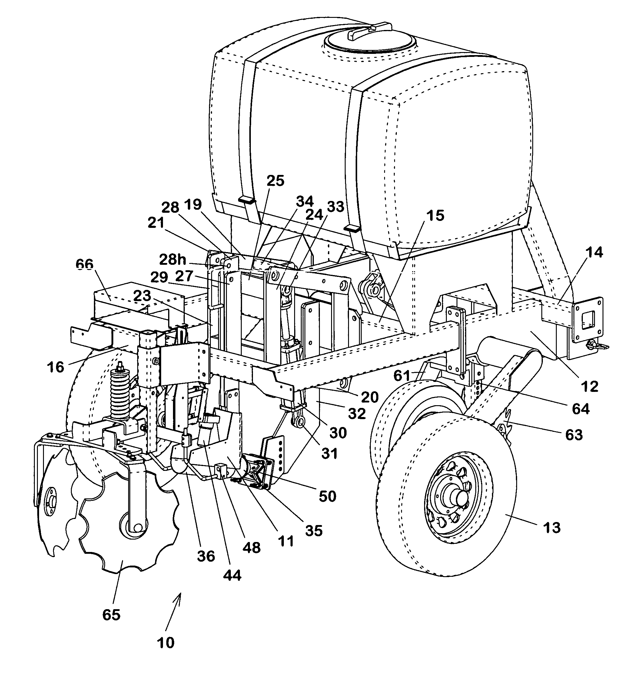
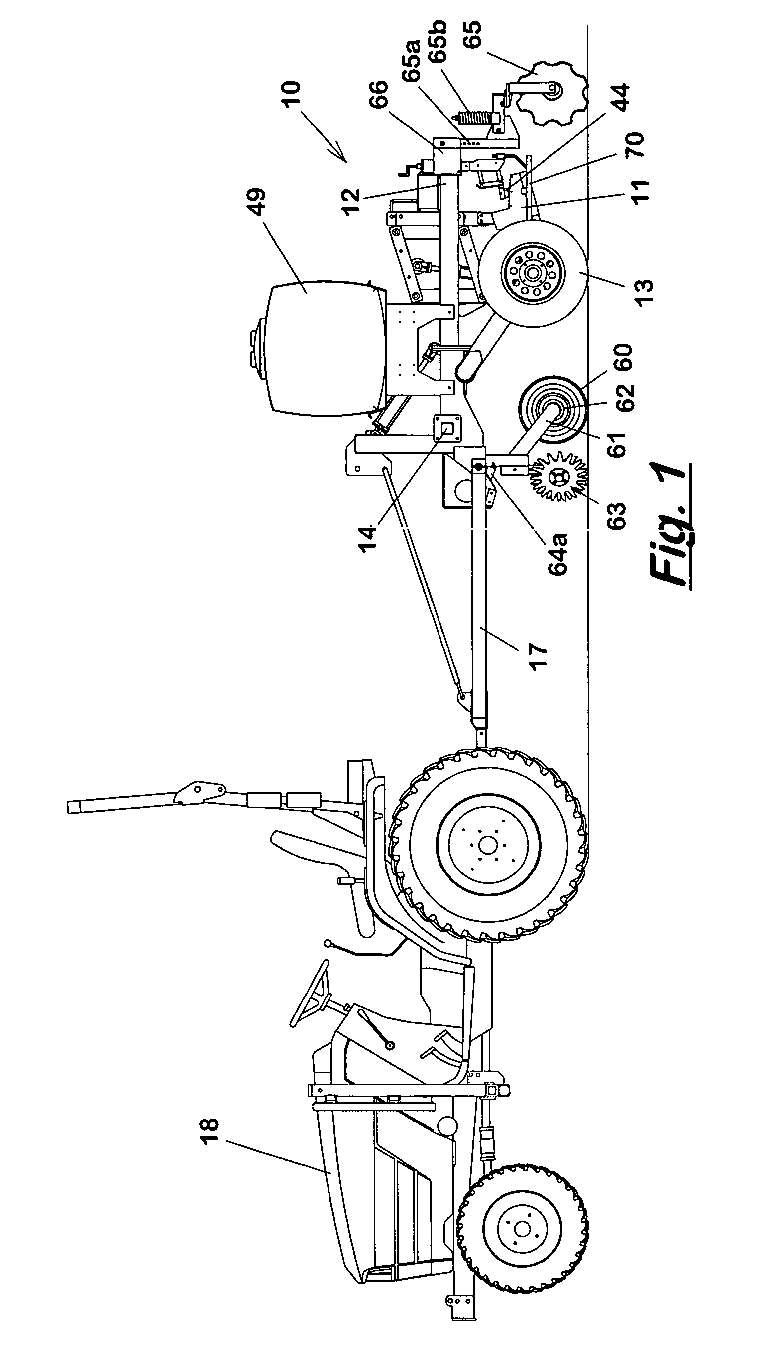
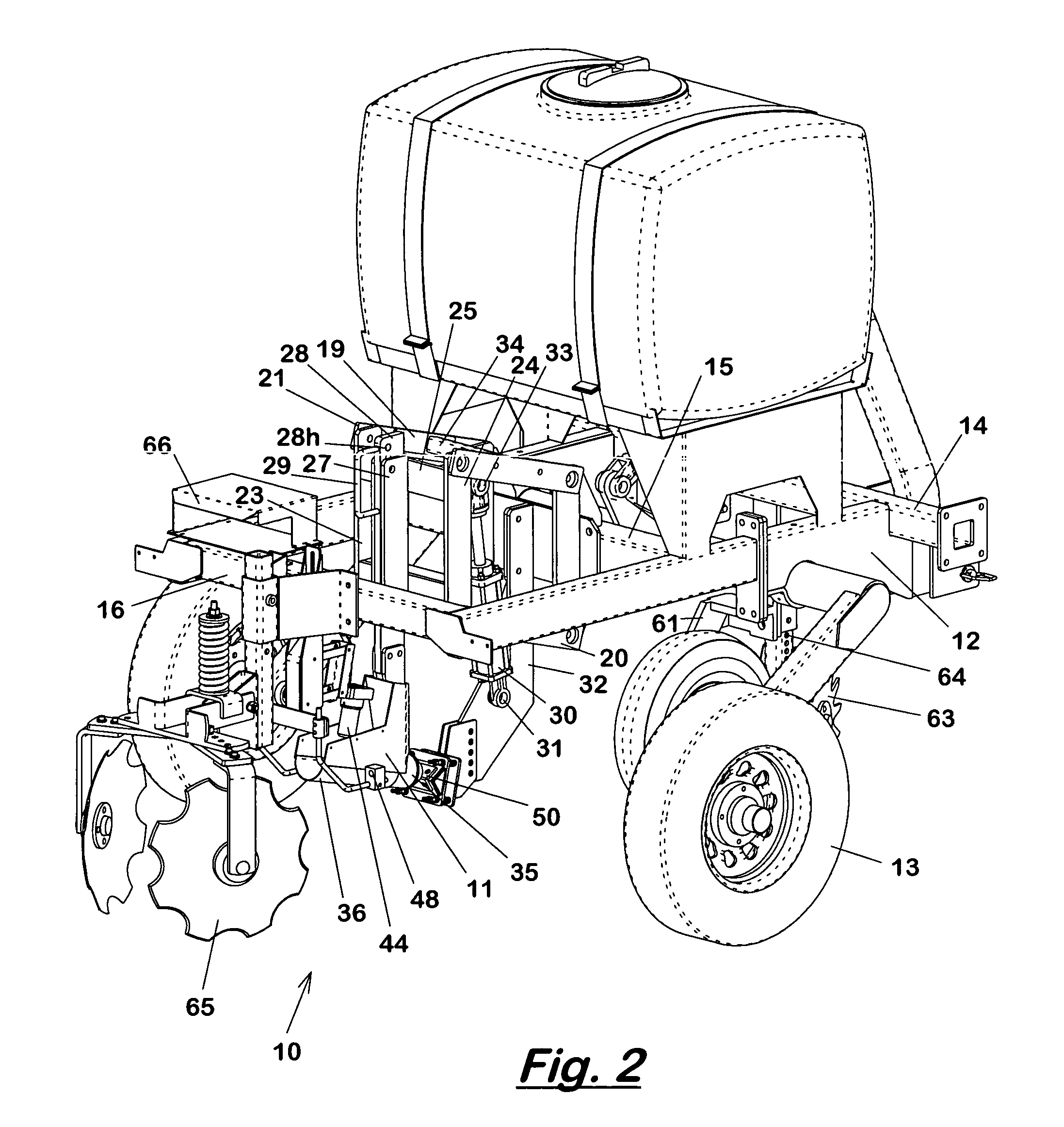
[0031] A soil sampling implement 10 and method according to the present invention will now be explained with reference to FIGS. 1 to 14 of the drawings. The implement 10 includes a sampler assembly 11 supported from an implement frame 12 for movement across a field to be sampled. The implement frame 12 can be a pull-type frame having gauge / transport wheels 13, tool bars 14, 15, 16, and a tongue 17 for connecting to a prime mover, such as a farm tractor 18. Alternatively, the implement frame can be a three-point mounted frame (not shown) for connecting to a corresponding three-point hitch structure on a tractor, or the implement frame can be self-propelled.

[0032] The sampler assembly 11 is mounted to the tool bar 15 of the implement frame 12 via an upper pair of links 19 and a lower pair of links 20. The upper and lower links 19, 20 together form a parallel linkage for supporting the sampler assembly 11. The rear ends 21, 22 of the upper and lower links 19, 20 are pivotally connecte...


PUM


Abstract

A soil sampling implement and method have a sampler assembly supported from an implement frame for movement across a field. The sampler assembly includes a tapered cylindrical cutting shoe and a soil collection trough. The cutting shoe has a leading cutting edge arranged for movement through soil in a horizontal direction to cut a cylindrical core sample. A sensing device is provided for measuring at least one soil property. The sampler assembly is moved between a lowered position in which the cutting shoe is positioned at a selected sampling depth, and a raised position in which the cutting shoe is positioned above the soil surface and a soil sample contained in the soil collection trough is brought into contact with the sensing device. A cutting shoe scraper engages and cleans the leading cutting edge of the cutting shoe when the sampler assembly is moved between the lowered and raised positions.

Description

RELATED APPLICATIONS [0001] This application claims priority of U.S. Provisional Application No. 60 / 544,139 filed on Feb. 11, 2004.FIELD OF THE INVENTION [0002] The present invention relates generally to methods and devices for analyzing and mapping soil properties within a field. In particular, the present invention relates to methods and devices for conducting on-the-go soil sampling operations. BACKGROUND OF THE INVENTION [0003] Accurately and affordably mapping soil properties within a field has proven challenging for precision agriculture practitioners. The sampling density needed to capture small spatial scale variability is impractical using conventional sampling and analysis methods. Those methods involve the insertion of a soil probe into the soil, retracting the probe, removing the soil from the probe, placing the soil into a bag, repeating the process until the bag contains typically 5 to 10 cores, labeling the bag, and sending the composited cores to a soil testing labor...

Claims


Application Information

Patent Timeline
IPC IPC(8): A01B79/00G01N1/08G01N33/24
CPCA01B79/005G01N2033/245G01N2001/021G01N1/08G01N33/245
Inventor DRUMMOND, PAULLUND, ERICCOLLINGS, KEVINCHRISTY, COLIN
Owner VERIS TECH
Learn More