Interactive gear engagement

Active Publication Date: 2005-08-04
FCA US
View PDF7 Cites 6 Cited by
  • Summary
  • Abstract
  • Description
  • Claims
  • Application Information

AI Technical Summary

Benefits of technology

[0003] Accordingly, one aspect of the present invention is to provide a system and method for providing an elevated cold engine idle speed while also minimizing driveline clunk.

Problems solved by technology

One source of noise is caused by the collective lash between components in the vehicle driveline.
As engine RPM increases, as is often the case when an engine is idling after a cold start, the driveline clunk becomes increasingly annoying.

Method used


Image

  • Interactive gear engagement
  • Interactive gear engagement
  • Interactive gear engagement

Examples


Embodiment Construction

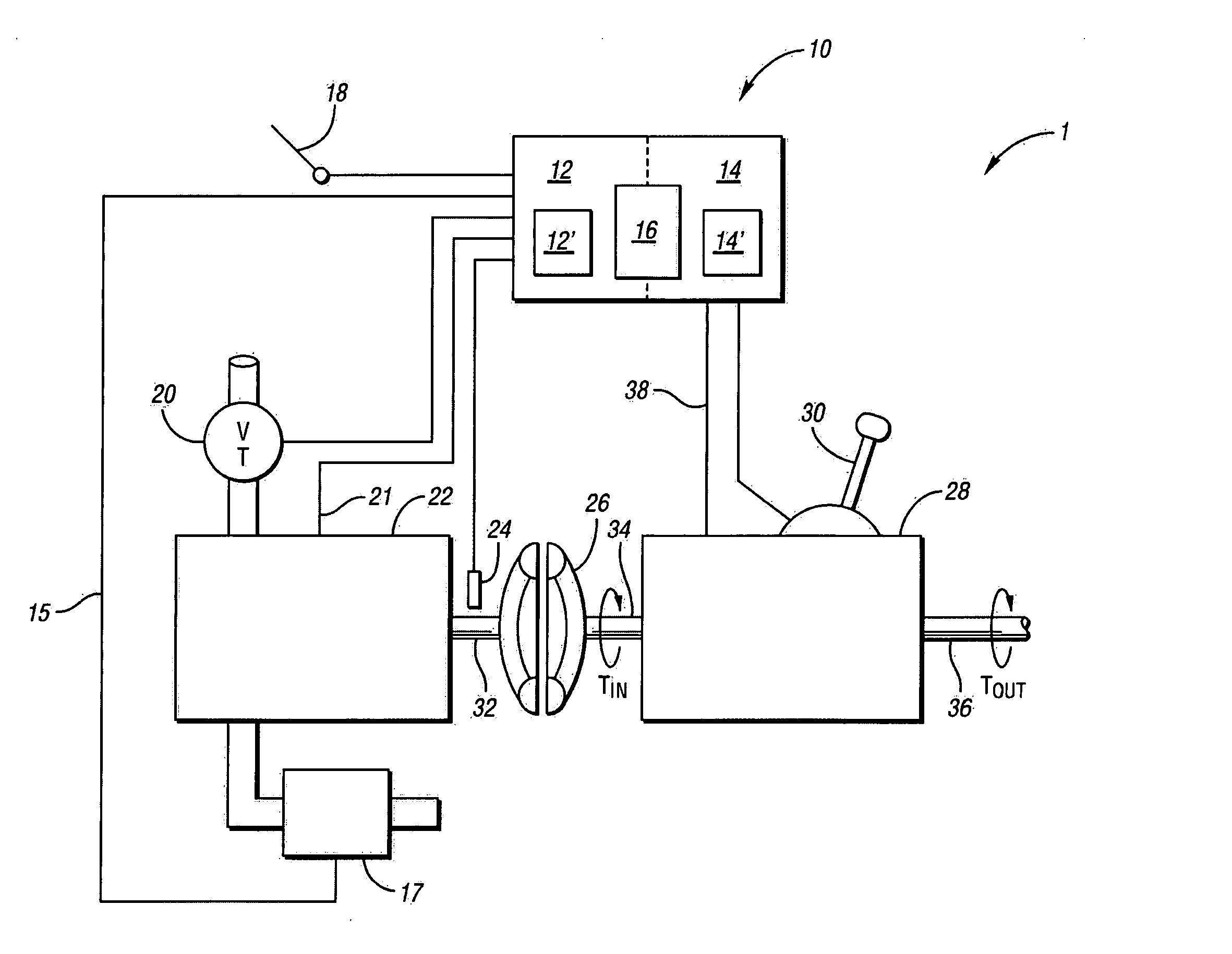
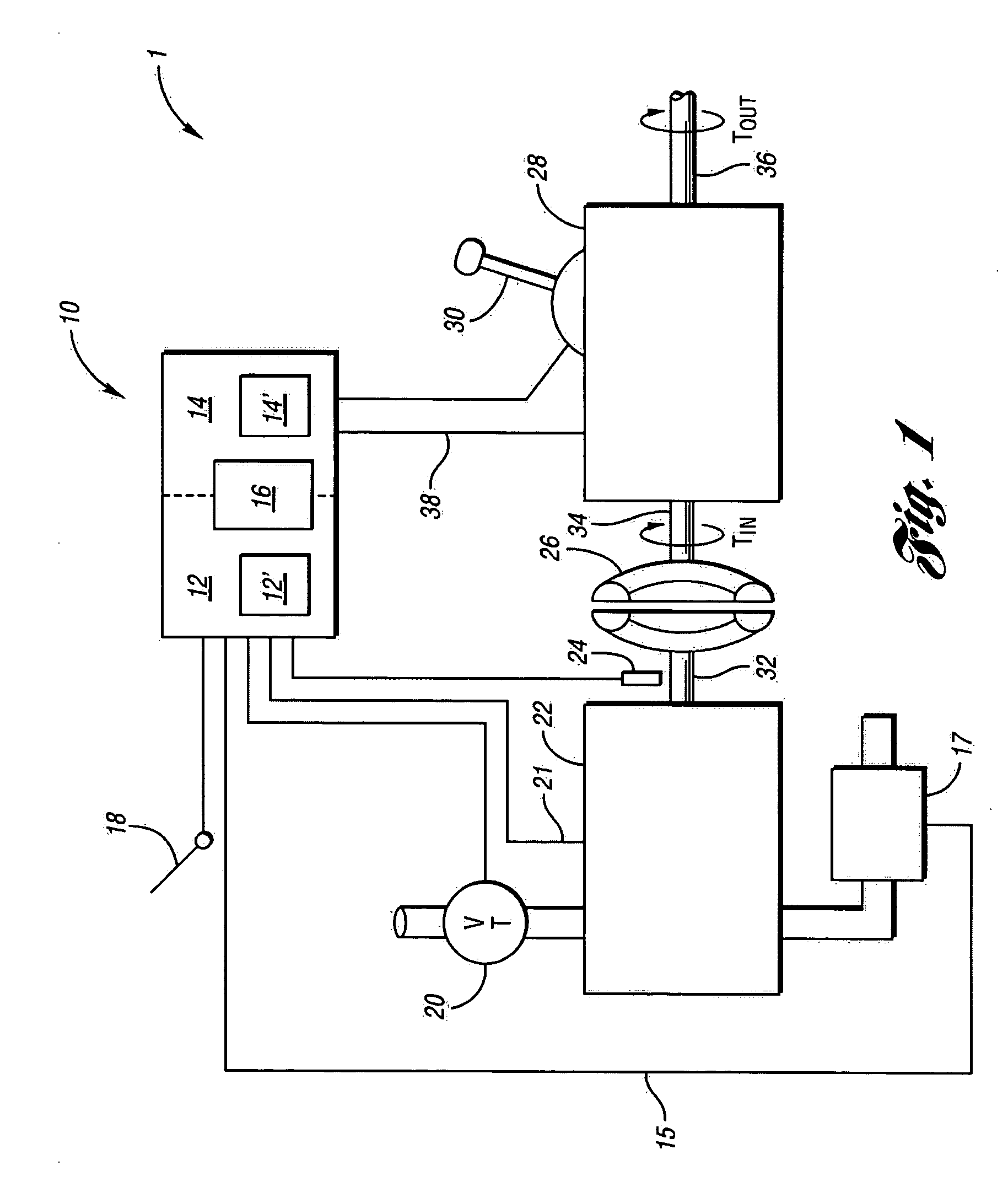
[0008] Turning now to FIG. 1, a block diagram of a vehicle powertrain 1 is shown. An engine 22 has a crankshaft 32, which is connected to one side of a viscous coupling 26. The other side of the viscous coupling 26 provides input torque TIN to an input shaft 34 of electronically controlled transmission 28. The transmission 28 provides output torque TOUT at output shaft 36, which is connected to the driveshaft and axles (not shown) as is known in the art. Transmission 28 also has at least one gear engagement control input 38 for engaging a drive gear and a neutral gear in the transmission. Engine 22 has an idle air control valve 20 for providing combustion air to the engine 22. The idle air control valve 20 is controlled by a powertrain control module (PCM) 10. A spark angle control line 21 from the PCM 10 controls the ignition angle of engine 21. Exhaust gas from engine 22 is routed through a catalyst 17 to reduce undesirable exhaust emissions.

[0009] The PCM 10 has an engine segmen...


PUM


Abstract

A vehicle powertrain has an engine coupled to an electronically-controlled automatic transmission. A method for controlling the vehicle powertrain during a transmission shift from a neutral gear to a drive gear detects a change in a signal indicative of a desired transmission gear change from a neutral gear to a drive gear. An engine idle speed is reduced by a predetermined RPM in response to the change in the signal. The transmission is shifted from the neutral gear into the drive gear upon the engine idle speed being reduced by the predetermined RPM.

Description

FIELD OF THE INVENTION [0001] This invention relates generally to controlling a vehicle powertrain, and, more particularly, to a system and method in which engine and transmission control segments communicate in order to control torque in the vehicle powertrain. BACKGROUND [0002] In motor vehicles it is desirable to control or reduce particular noises and vibrations created in the vehicle powertrain. One source of noise is caused by the collective lash between components in the vehicle driveline. As the vehicle is changed from a neutral gear to a drive gear, the transmission applies torque to the driveline which causes its components to move and take-up the collective lash. As the components move, the driveline emits a noise which is commonly referred to as driveline clunk. As engine RPM increases, as is often the case when an engine is idling after a cold start, the driveline clunk becomes increasingly annoying. However, the increased engine RPM is desirable to increase the heating...

Claims


Application Information

Patent Timeline
IPC IPC(8): B60W30/18F16H59/74F16H61/04
CPCB60K2741/065B60W30/18B60W2510/068B60W2710/065F16H61/0437Y10T477/653F16H2061/0488Y10T477/677Y10T477/6808Y10T477/67F16H2059/144B60W10/04B60W10/11B60W30/1819
Inventor FETT, DENNIS W.POUBLON, MARK J.RZEPECKI, JOHN M. IILOWE, GARY K.
Owner FCA US
Why Eureka
Try Eureka