Cam bar centering mechanism
- Summary
- Abstract
- Description
- Claims
- Application Information
AI Technical Summary
Benefits of technology
Problems solved by technology
Method used
Image
Examples
Embodiment Construction
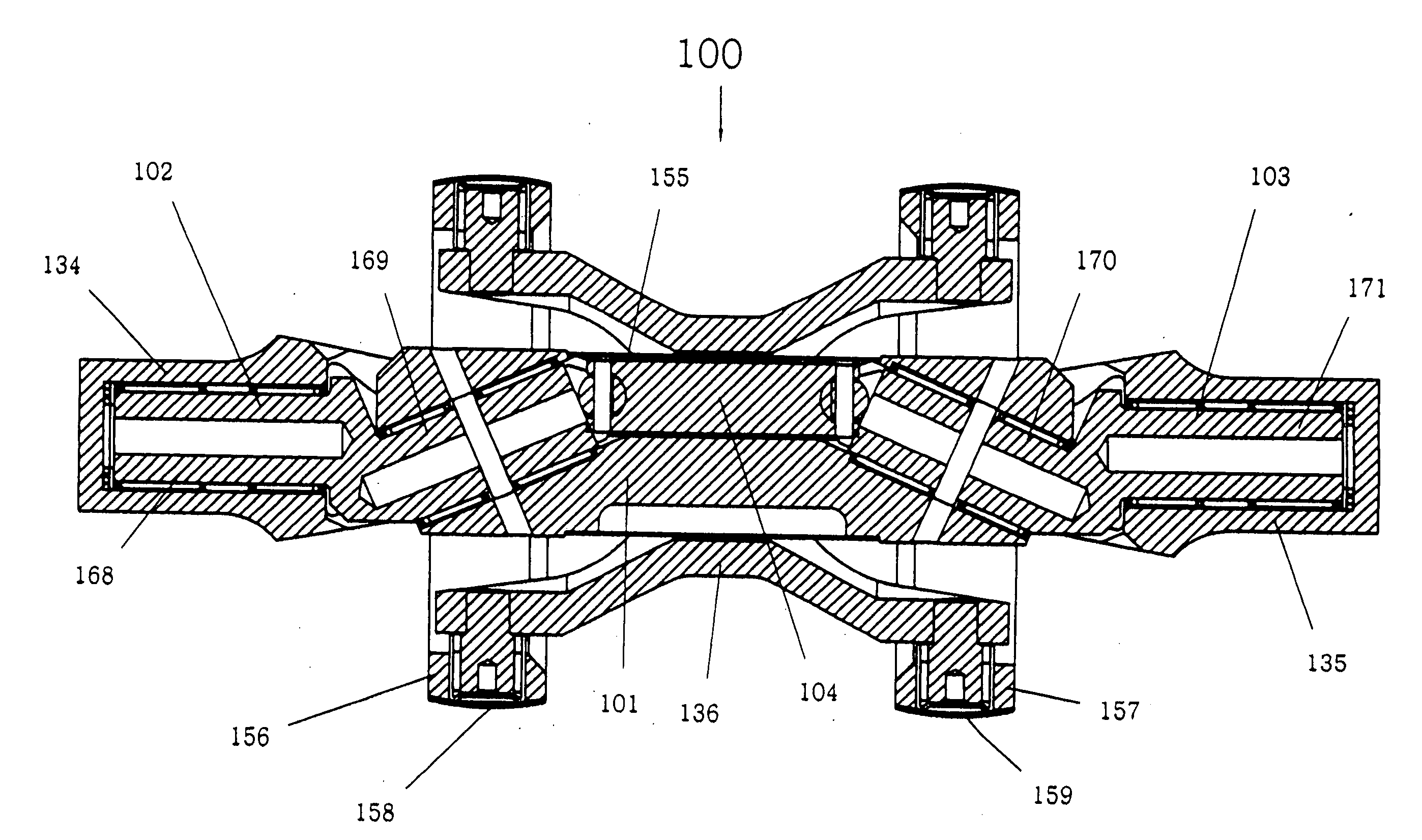
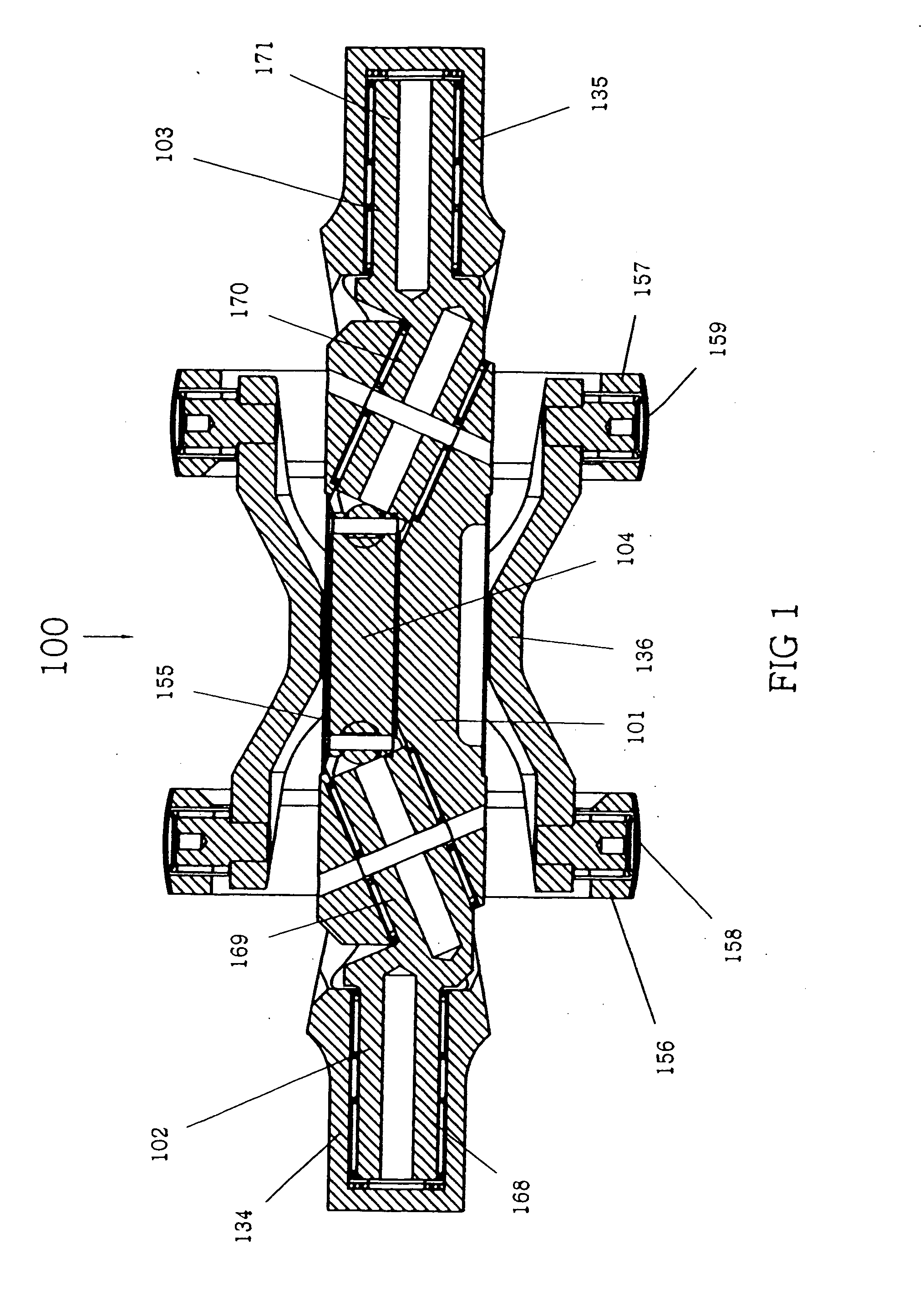
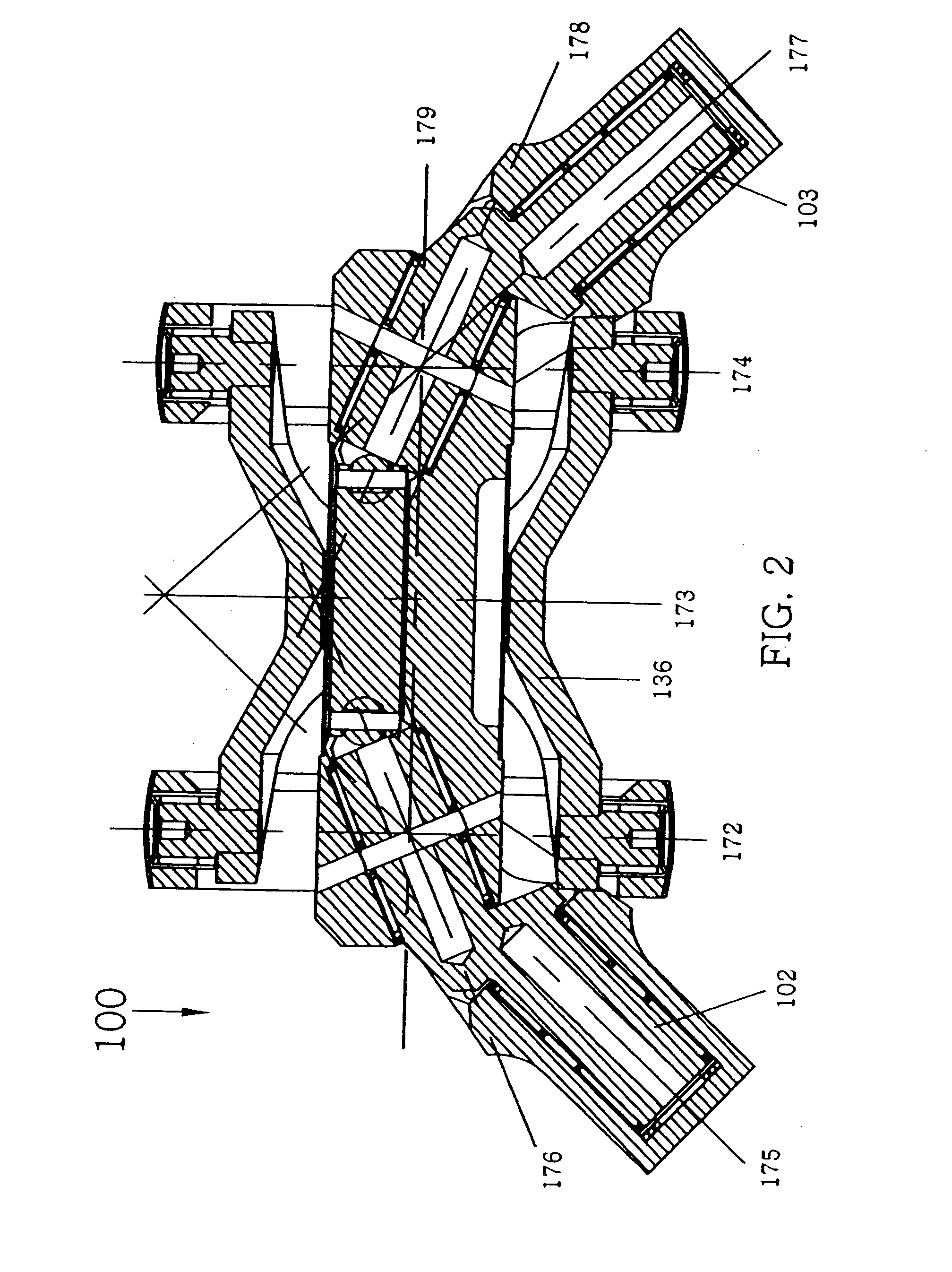
[0044] Universal joints 100, 200, 300, 400 and 500 include respective centering mechanisms 100A, 200B, 300C, 400D for supporting the universal joints and forcing the two joint halves to operate at the same angle thereby causing the joint to operate at constant velocity at all angles. For example, each shaft 134, 135 of the joint 100 is rotatably connected to the centering mechanism 100A. Movement of one of the shafts 134, 135 at an angle relative to the longitudinal axis of the connecting yoke 136 is transmitted to the other shaft 135, 134 by the centering mechanism 100A and the centering mechanism 100A causes the other shaft 135, 134 to likewise move at the same angle relative to the longitudinal axis of the connecting yoke 136. The centering mechanism 100A includes cam rods 102, 103 supported within a cam tube 101, which arrangement of bearings allows a full range of movement of the shafts 134, 135 at angles of 90°.
[0045] Universal joint 100 can be assembled by the following meth...
PUM
 Abstract
Description
Claims
Application Information
 - R&D
- Intellectual Property
- Life Sciences
- Materials
- Tech Scout
- Unparalleled Data Quality
- Higher Quality Content
- 60% Fewer Hallucinations
Browse by: Latest US Patents, China's latest patents, Technical Efficacy Thesaurus, Application Domain, Technology Topic, Popular Technical Reports.
© 2025 PatSnap. All rights reserved.Legal|Privacy policy|Modern Slavery Act Transparency Statement|Sitemap|About US| Contact US: help@patsnap.com


