
Amphibious vehicle

a technology of amphibious vehicles and propulsive elements, applied in the direction of propulsive elements, water acting propulsive elements, vessel construction, etc., can solve the problems of vehicle bottom out, vehicle is not able to make a smooth transition, and the driver may make an error in judging the depth of water

Inactive Publication Date: 2005-08-04
GIBBS TECH
View PDF5 Cites 17 Cited by
  • Summary
  • Abstract
  • Description
  • Claims
  • Application Information

AI Technical Summary

Benefits of technology

[0007] Thus, in accordance with a first aspect of the present invention, there is provided an amphibious vehicle adapted for use on land and on water, the vehicle having at least one system which is actuated or has its mode of operation changed when the vehicle changes from a land use mode to a water borne mode or vice versa, characterised in that the vehicle further comprises sensor means adapted such that in use it produces an output signal which varies in relation to the proportion of the mass of the vehicle which is buoyantly supported by a body of water. In accordance with a second aspect of the invention, there is provided an amphibious vehicle having a body, and a plurality of wheels, each ...

Problems solved by technology

However, it is essential that the wheel retraction system is not operated before the vehicle is in a sufficient depth of water that the mass of the vehicle can be supported by the water when the wheels are fully retracted.
For example, it is possible for the driver to make an error in judging the depth of the water.
This may result in the wheels being retracted while the vehicle is still in relatively shallow water such that the vehicle bottoms out as the wheels are retracted.
Furthermore, it is not possible for the vehicle to make a smooth transition from land use to water use, as it is necessary for the driver to continually check the depth of the water prior to operating the wheel retraction system.
Each of these methods has fundamental drawbacks.
Any sensor on the outside of the vehicle body is potentially subject to mechanical damage, and could be bridged by marine debris.
Furthermore, a single sensor (Aquastrada do not disclose its position) does not ensure that the entire vehicle is afloat.
Westphalen's float switch is liable to delayed action, and to blockage or seizure through ingress of debris.

Method used


Image

  • Amphibious vehicle
  • Amphibious vehicle
  • Amphibious vehicle

Examples


Embodiment Construction

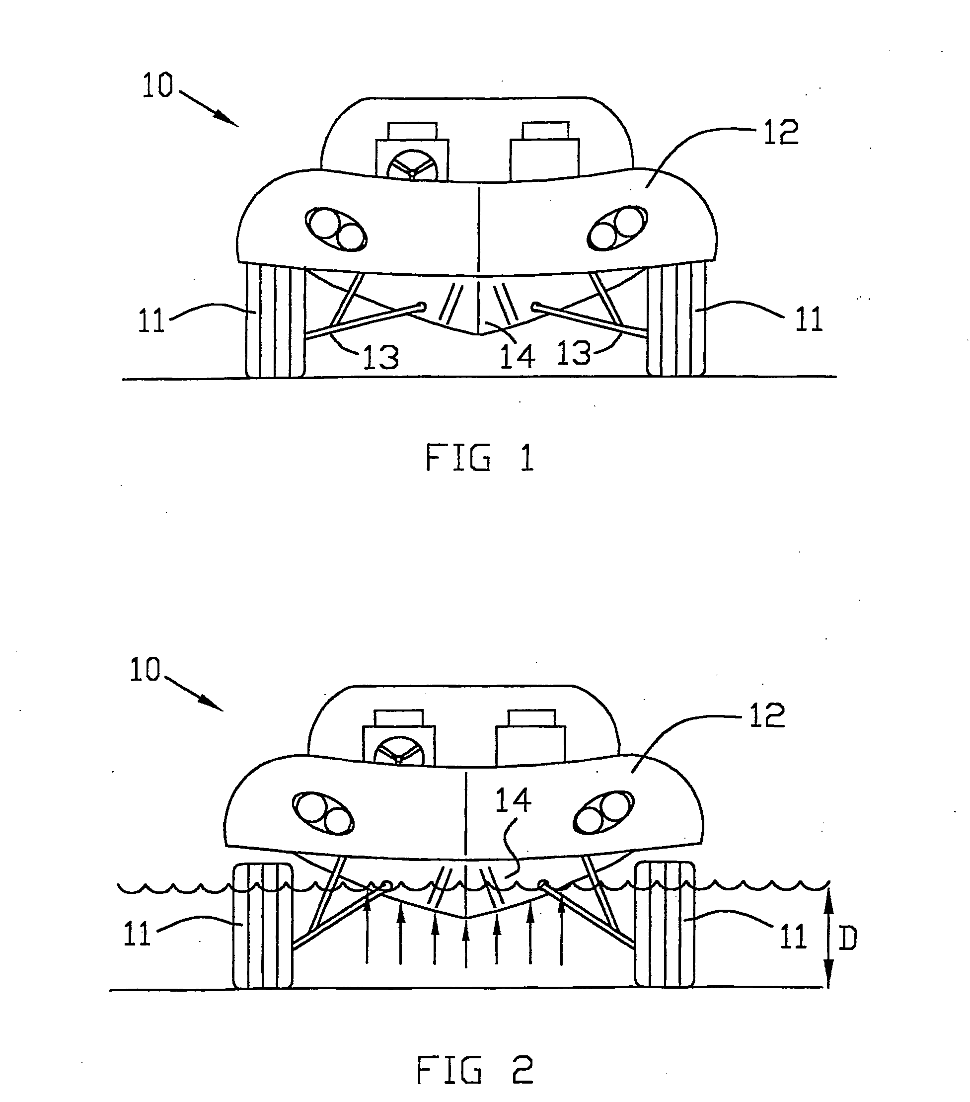
[0016]FIGS. 1 and 2 show an amphibious vehicle, indicated generally at 10. The vehicle has wheels 11, each of which is mounted to a vehicle body 12 by means of a respective suspension assembly 13. Although only two wheels 11 are shown in FIG. 1, it will be understood that in a preferred embodiment, the vehicle has four wheels, two at the front and two at the rear, as shown in FIG. 4. However, the precise number of wheels on the vehicle is not essential to the invention.

[0017] In FIG. 1, the vehicle is on land with all the vehicle mass being supported by the suspension. The wheels 11 are at their normal relative position with respect to the vehicle body 12.

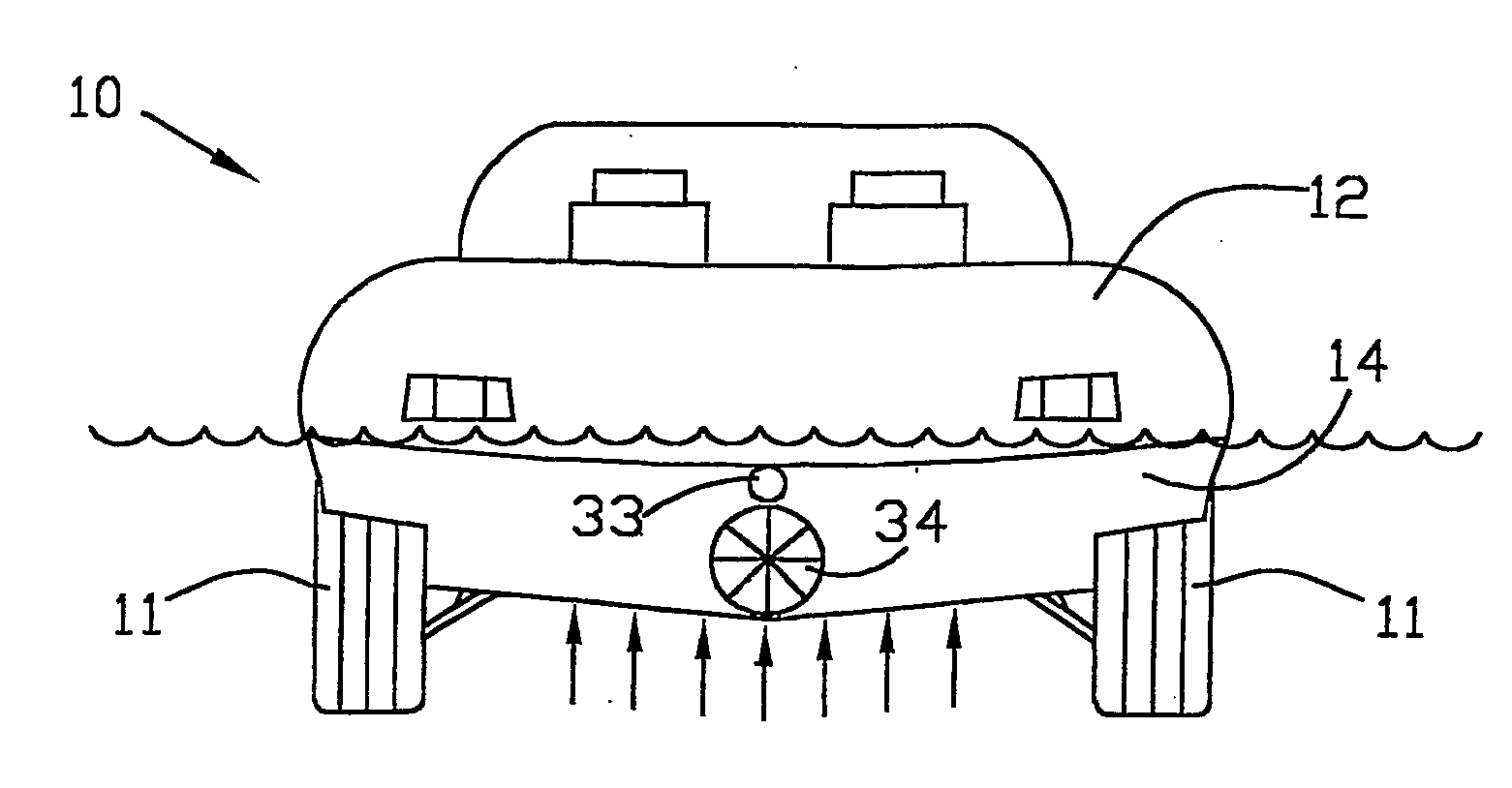
[0018]FIG. 2 shows the amphibious vehicle in water of a depth “D”. As the vehicle 10 enters the water, the mass of the vehicle becomes partially supported by the buoyancy of the hull 14 (as indicated by the arrows), reducing the load on the vehicle suspension. As the depth of the water increases, the proportion of the mass of the...


PUM


Abstract

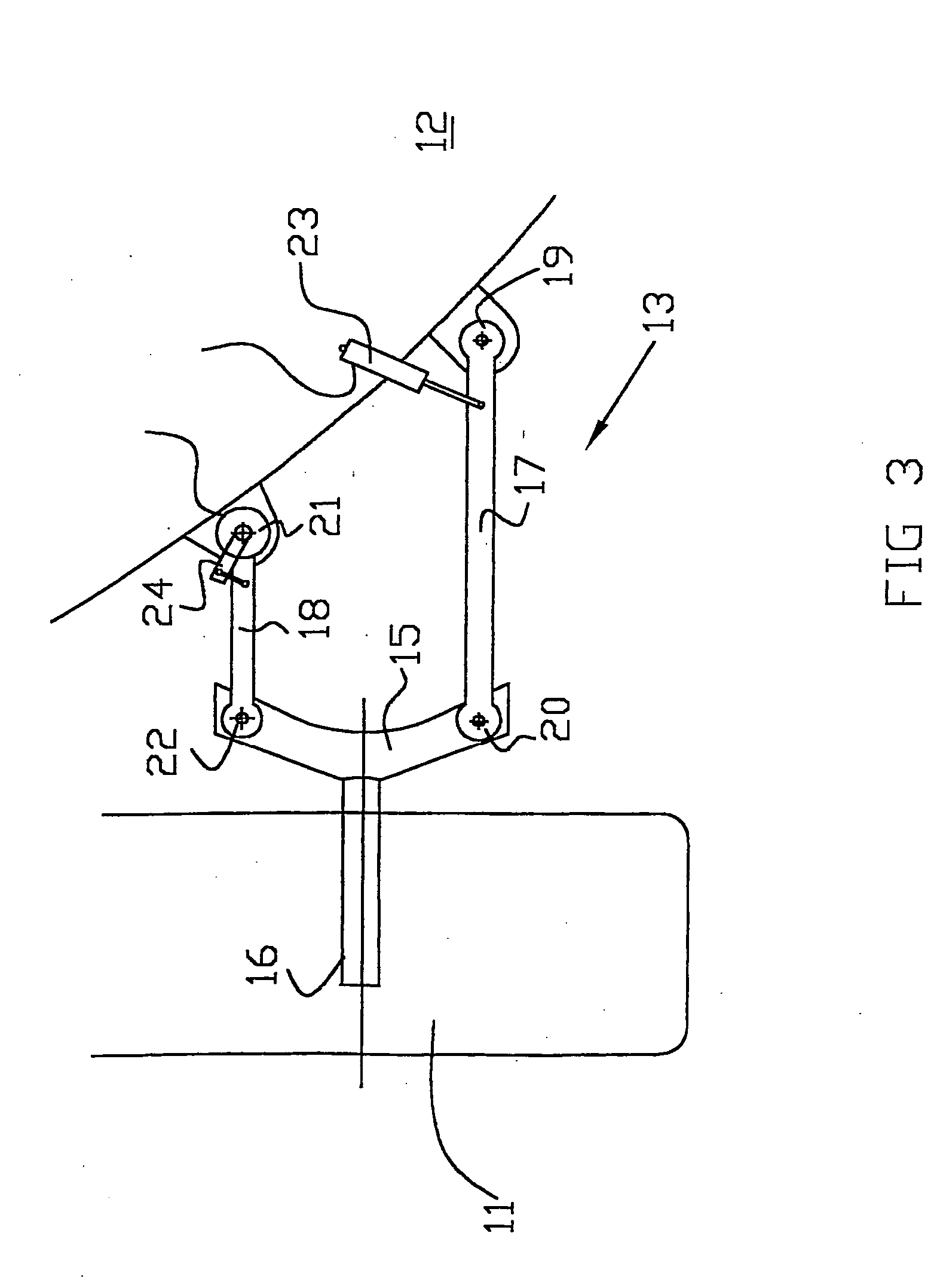
Amphibious vehicle has at least one system which is actuated or has its mode of operation changed when the vehicle changes from land mode to water mode or vice versa. The vehicle comprises sensor means which produce an output signal which varies in relation to the proportion of the mass of the vehicle which is buoyantly supported by a body of water. The sensors may sense the position of a wheel relative to the body of the vehicle. This may be achieved by checking the position of a suspension member. The sensor means may comprise a linear sensor or a rotary sensor. The sensor may comprise a potentiometer. Control means may average the output of the sensor over time. Where several sensors are used, control means may process output signals from each sensor to provide an overall output signal. A water presence sensor, such as a thermistor, may be used to provide a second control signal.

Description

BACKGROUND OF THE INVENTION [0001] The present invention relates to an amphibious vehicle which is adapted for use both on land and on water. In particular, the present invention relates to an amphibious vehicle having systems which need to be activated or have their mode of operation changed when the vehicle leaves land and enters water or vice versa. [0002] Known amphibious vehicles often comprise systems which must be actuated or have their mode of operation changed when the vehicle changes from a land use mode to a water borne mode or visa versa. For example, it is known to provide amphibious vehicles with wheels and associated suspension assemblies which can be moved from a protracted position, in which they support the vehicle for land use, to a retracted position, in which the wheels are moved above the water line for use of the vehicle in water. Such an amphibious vehicle is known for example from European patent No. EP 0 742 761. When the vehicle leaves land and enters a bo...

Claims


Application Information

Patent Timeline
IPC IPC(8): B60F3/00
CPCB60F2301/04B60F3/00
Inventor DARBY, CHRISTOPHER PAULGOODWIN, TIMOTHY RICHARD
Owner GIBBS TECH
Learn More