
Method and device for monitoring a data transmission

a data transmission and data technology, applied in the field of methods and devices for monitoring a data transmission, can solve the problems of increased cost at a higher error rate, inability to confirm messages, and inability to monitor messages, and achieve the effect of improving network security

Active Publication Date: 2005-07-28
ROBERT BOSCH GMBH
View PDF7 Cites 8 Cited by
  • Summary
  • Abstract
  • Description
  • Claims
  • Application Information

AI Technical Summary

Benefits of technology

[0011] A confirmed communications service or a confirmed data transmission is advantageously achieved at little cost.
[0021] Use of a computer program on a data medium for applying the method according to the present invention represents a particularly advantageous implementation and application of the present invention.
[0022] The present invention, further described in the following, results in a very efficient improvement in network security, since the network may be operated in a confirmed transmission mode, and a conventional, highly compatible transmission protocol, the ISO 15765-2 in particular, may be used and at the same time network users, which do not contain the expansion of the standard protocol according to the present invention, may still be operated within the existing network.

Problems solved by technology

However, if messages are exclusively transmitted in an event-driven manner, an absent confirmation of the message is not acceptable.
Possible approaches to the problem of the absent confirmation, in CAN-based systems in particular, result from the fact that a transmission protocol, exclusively provided for this purpose, is used, this transmission protocol, however, having the disadvantage of being incompatible with protocols required for a plurality of applications within the diagnostic scope in the motor vehicle, or that the required confirmation is executed on higher protocol layers, known as an additional security layer, resulting disadvantageously in substantially higher costs at a higher error rate, as well as in greater inefficiency, in particular due to a higher bus load.

Method used


Image

  • Method and device for monitoring a data transmission
  • Method and device for monitoring a data transmission
  • Method and device for monitoring a data transmission

Examples


Embodiment Construction

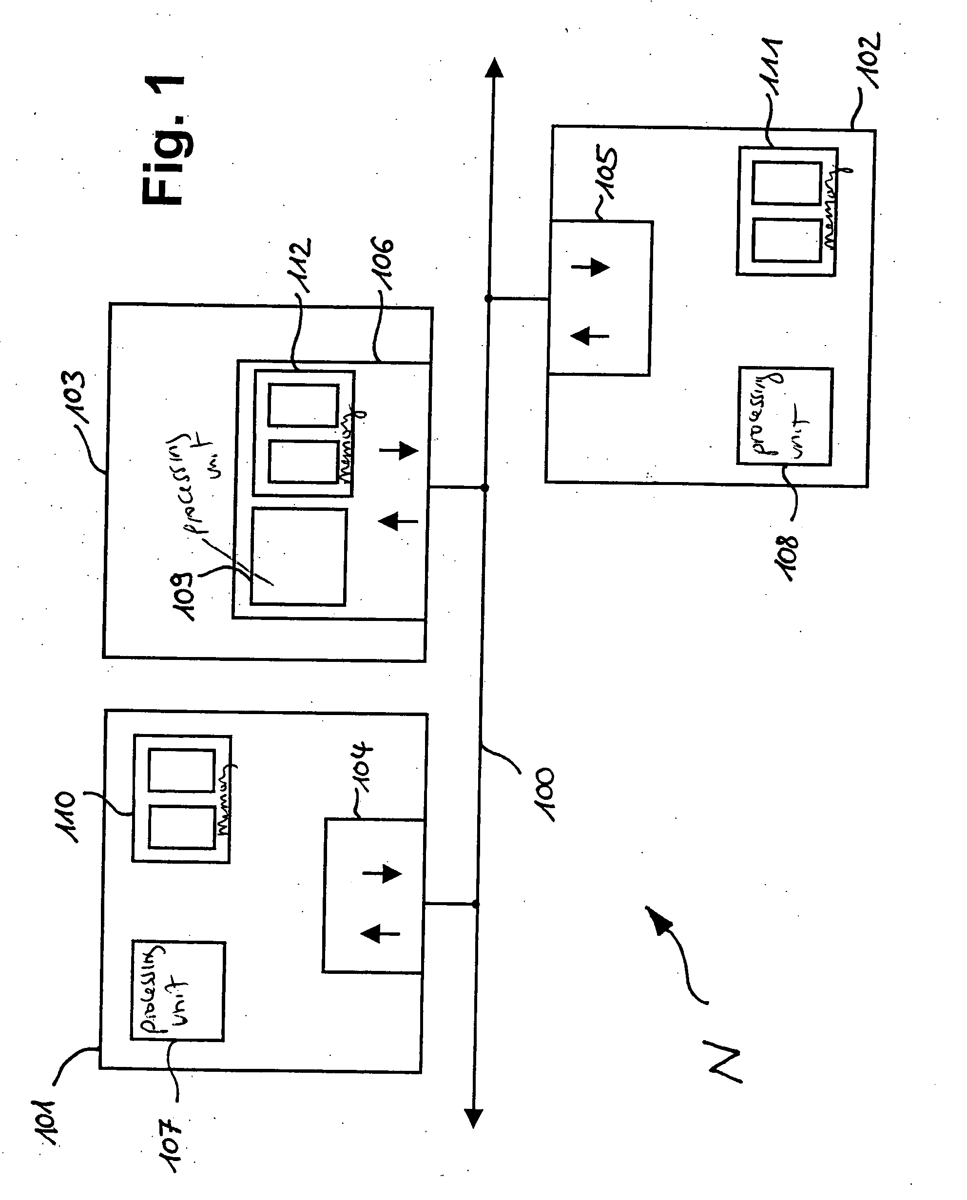
[0029]FIG. 1 shows a network N having a bus connection 100 and at least two users 101 and 102. Additional users, like 103 here, are optional, but of course possible according to the present invention. The network or bus system, in particular corresponding to ISO 15765-2, is a CAN system for example, in a vehicle in particular. Other applications, in particular in the areas of machine tools, industrial goods, and durable consumer goods, as well as other bus systems are of course possible.

[0030] Furthermore, the transmission protocol is based on the aforementioned ISO 15765-2, in particular ISO / DIS 157652-2, as of Nov. 30, 1999 (ISO / TC 22 / SC 3 / WG 1 / TF 2 N 124). However, any other protocol, which has the characteristics of this ISO standard utilized according to the present invention and does not offer a confirmed service, is also conceivable.

[0031] The bus users in the example in FIG. 1 include a bus interface 104, 105, and 106, processing units 107, 108, and 109, as well as memory ...


PUM


Abstract

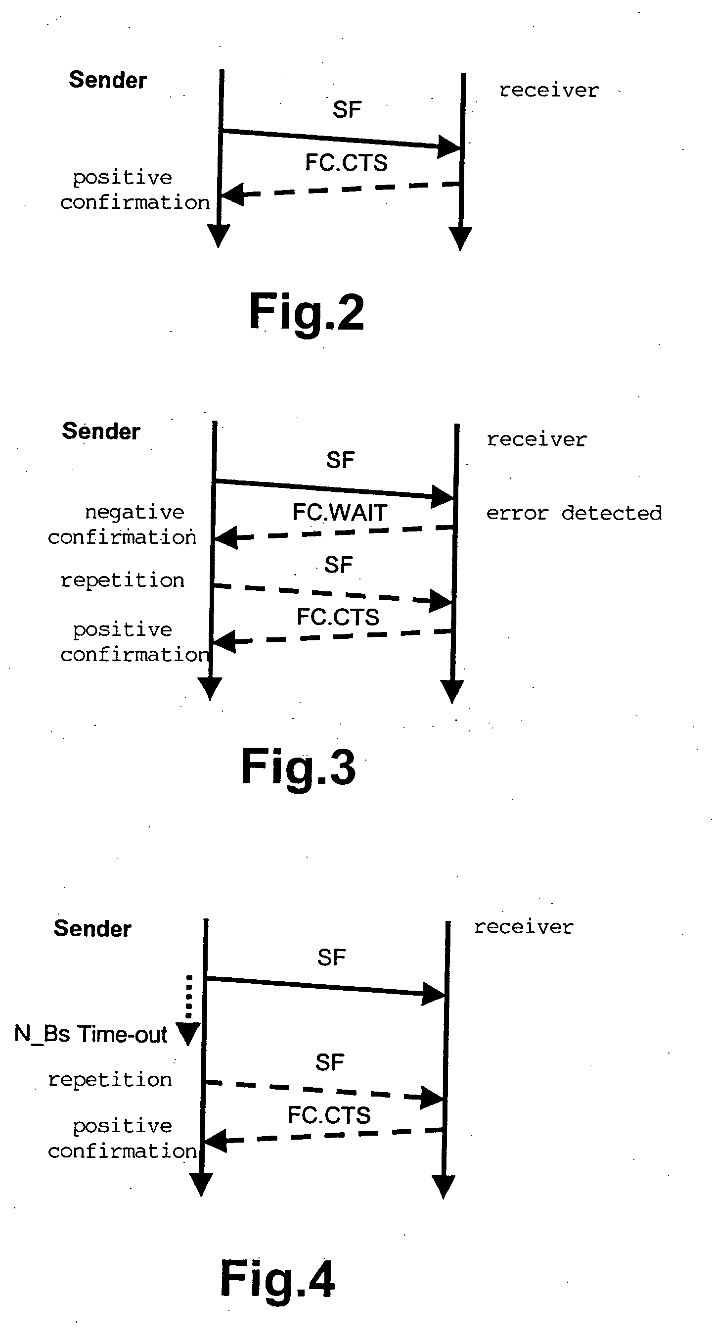
A method for monitoring a data transmission between at least two network users, in particular according to the ISO 15765-2 transmission protocol, is described, at least one sender transmitting data to at least one receiver in the form of data telegrams, a data transmission taking place via at least one data telegram and the receiver transmitting at least one flow control telegram to the sender when the data of a data transmission is transmitted in a segmented manner in a first data telegram and at least one subsequent data telegram, an additional flow control telegram being transmitted from the receiver to the sender after the last data telegram of a data transmission.

Description

CROSS REFERENCE TO RELATED APPLICATIONS [0001] The present application is a continuation-in-part of International Application PCT / DE03 / 02126 filed on Jul. 21, 2003 (priority to which is claimed under 35 U.S.C. § 120), and expressly incorporated herein by reference in its entirety. The present application also claims priority under 35 U.S.C. § 119 to Application No. 102 34 348.9, filed in the Federal Republic of Germany on Jul. 26, 2002, and expressly incorporated herein by reference in its entirety.FIELD OF THE INVENTION [0002] The present invention relates to a method and a device for monitoring a data transmission between at least two network users. BACKGROUND INFORMATION [0003] Methods for data transmissions, the corresponding transmission protocols in particular, are used everywhere where large amounts of data, referred to in the following as messages, are to be securely transmitted in small packets, referred to in the following as data telegrams or also data frames. A CAN teleg...

Claims


Application Information

Patent Timeline
IPC IPC(8): G06F15/16H04L12/40H04L12/56
CPCH04L12/40032H04L2012/40215H04L47/10H04L12/407
Inventor RODE, DETLEFZURMUEHL, UWE
Owner ROBERT BOSCH GMBH
Learn More