
Method for modelling the production of hydrocarbons by a subsurface deposit which are subject to depletion

a technology of hydrocarbon production and subsurface deposit, which is applied in the direction of seismology for waterlogging, borehole/well accessories, instruments, etc., can solve the problem that the model of the production by depletion poses a specific problem, the relative permeability kr measured in the laboratory on samples containing viscous oils cannot be directly used in numerical reservoir simulation, and the use of a large number of parameters that cannot be directly measured

Active Publication Date: 2005-07-28
INST FR DU PETROLE
View PDF1 Cites 20 Cited by
  • Summary
  • Abstract
  • Description
  • Claims
  • Application Information

AI Technical Summary

Benefits of technology

[0012] The modelling method according to the invention allows simulation of production by an underground reservoir under the effect of depletion. It affords an excellent compromise between the accuracy to the physical mechanisms and modelling simplicity, in particular a small number of parameters that can be determined from a single laboratory experiment.
[0019] By means of a two-stage procedure structured on a common significant parameter characterizing the nucleation of the gas phase, which is valid for the experimentally studied samples as well as for the rocks of the reservoir, the first stage being carried out with reference to laboratory measurements, it is possible to construct a predictive modelling tool allowing realistic representation of the conditions of flow of the viscous fractions of the oil in place in the reservoir.

Problems solved by technology

Modelling of the production by depletion poses a specific problem for numerical simulations.
Unlike the water and oil drive production methods, the relative permeabilities Kr measured in the laboratory on samples containing viscous oils cannot be directly used in numerical reservoir simulations.
These models have been tested only for light oils and they do not take into account dispersed gas flow.
On the other hand, it uses a large number of parameters that cannot be directly measured, such as the number and the size of the bubbles.
Furthermore, this model does not deal with the flow of the phases and the mass transfer throughout an experiment.
It is difficult to interpret experiments in terms of physical parameters and therefore to be predictive.
It is therefore impossible to predict parameters under reservoir conditions.

Method used


Image

  • Method for modelling the production of hydrocarbons by a subsurface deposit which are subject to depletion
  • Method for modelling the production of hydrocarbons by a subsurface deposit which are subject to depletion
  • Method for modelling the production of hydrocarbons by a subsurface deposit which are subject to depletion

Examples


Embodiment Construction

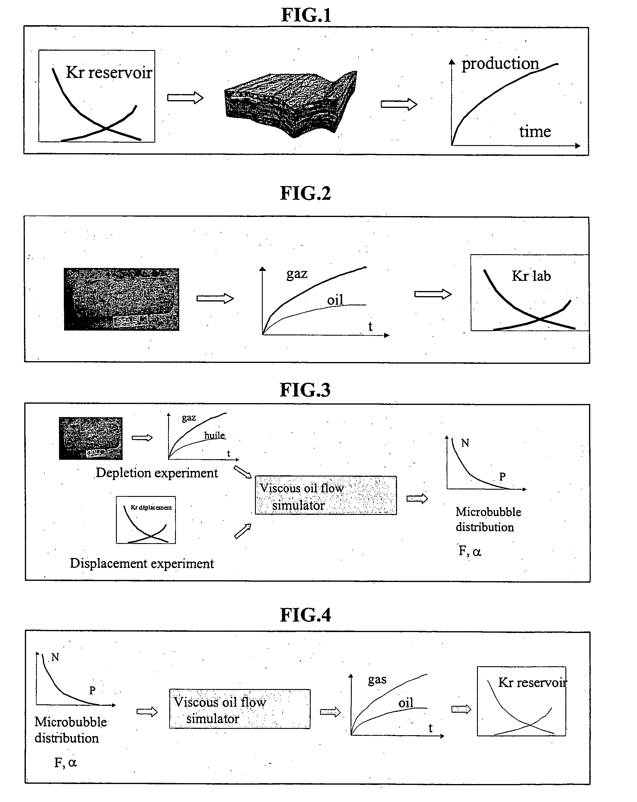
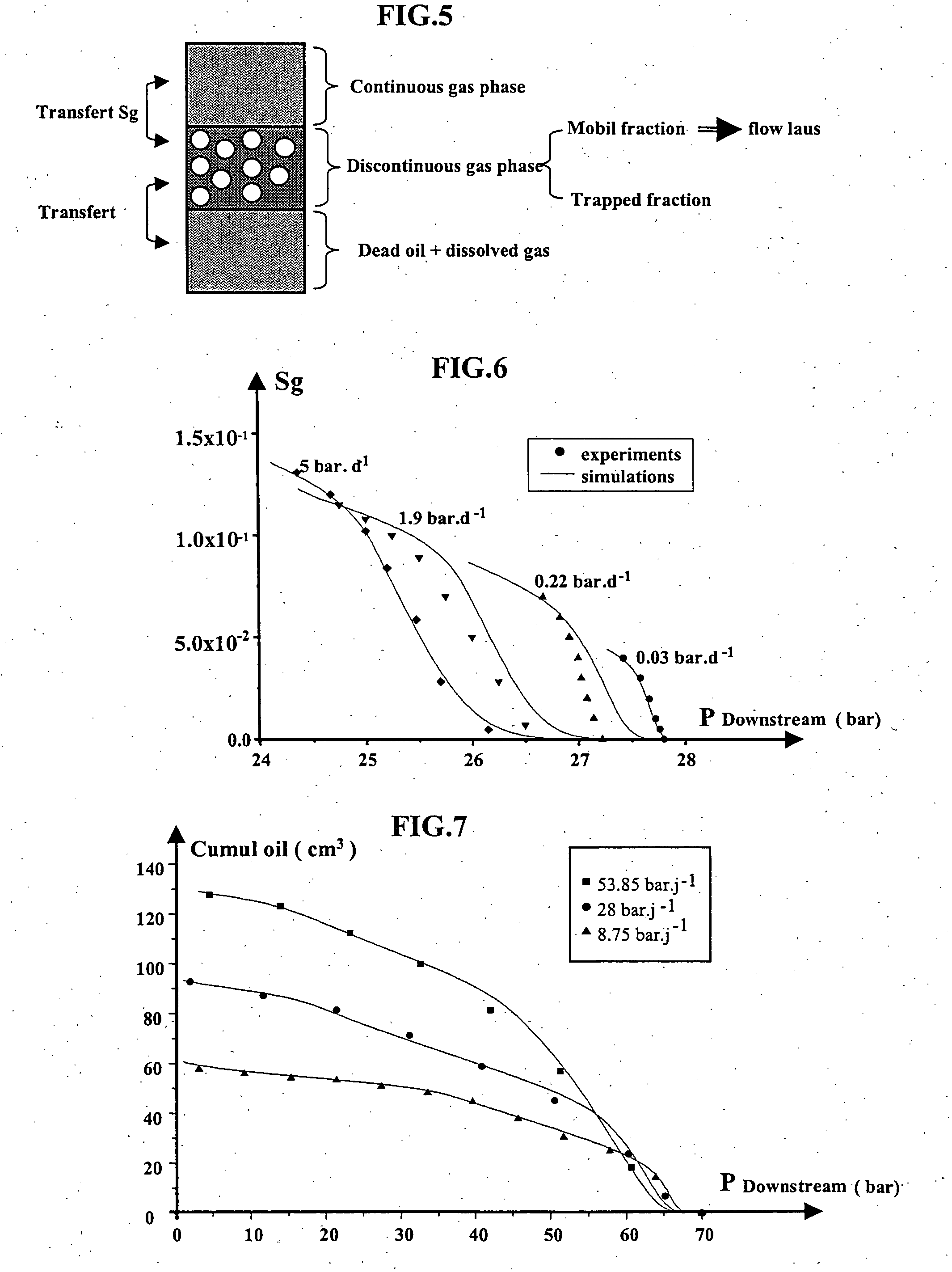
[0029] A first important point of the method of the invention relates to the “off-equilibrium” aspect of the light component transfer. It is based on modelling of the gas phase nucleation allowing prediction of the density of the bubbles and the pressure at which they appear. A law of distribution of the number of pre-existing “nuclei” or microbubbles as a function of the pressure is suggested. This empirical law N(P) takes into account the properties of the solid (surface roughness), the properties of the fluids and the physico-chemical interactions between the fluids and the solid (wettability for example). A relation form, for example exponential or power law, is imposed from the published measurements and the few parameters of this law (threshold pressure, exponent of the power law) are determined from the experiment by calibration. This law is considered valid at the laboratory stage as well as at the reservoir stage. From knowledge of this law N(P) and of the thermodynamic pro...


PUM


Abstract

A method for forming a model simulating production, by an underground reservoir subject to depletion, of hydrocarbons comprising notably relatively high-viscosity oils. From laboratory measurements of the respective volumes of oil and gas produced by rock samples from the reservoir subject to depletion, and the relative permeabilities (Kr) of rock samples to hydrocarbons, a model of the formation and flow of the gas fraction is used to determine a volume transfer coefficient (hv) by means of an empirical function representing the distribution of nuclei that can be activated at a pressure P (function N(P)) which is calibrated with reference to the previous measurements. Considering that the nuclei distribution N(P) in the reservoir rocks is the same as the distribution measured in the laboratory, the numerical transfer coefficient corresponding thereto in the reservoir at selected depletion rates is determined using the gas fraction formation and flow model, which allows predicting the relative permeabilities in the reservoir and the production thereof which is useful for reservoir engineering. Method for forming a model allowing to simulate the production, by an underground reservoir subjected to depletion, of hydrocarbons comprising notably relatively high-viscosity oils. From laboratory measurements of the respective volumes of oil and gas produced by rock samples from the reservoir and subjected to depletion, and the relative permeabilities (Kr) of rock samples to hydrocarbons, a model of the formation and flow of the gas fraction is used to determine a volume transfer coefficient (hv) by means of an empirical function representing the distribution of nuclei that can be activated at a pressure P (function N(P)) which is calibrated with reference to the previous measurements. Considering that the nuclei distribution N(P) in the reservoir rocks is the same as the distribution measured in the laboratory, the numerical transfer coefficient corresponding thereto in the reservoir at selected depletion rates is determined using the gas fraction formation and flow model, which allows to predict the relative permeabilities in the reservoir and the production thereof. Applications notably reservoir engineering.

Description

BACKGROUND OF THE INVENTION [0001] 1. Field of the Invention [0002] The present invention relates to a method for modelling the production of hydrocarbons comprising notably relatively high-viscosity oils by petroleum reservoirs subjected to decompression or depletion. [0003] 2. Description of the Prior Art [0004] The development of hydrocarbon reservoir production simulation generally involves several stages. Laboratory experiments are first interpreted. Then, the phenomena are modelled on the laboratory scale before an extrapolation is carried out on the reservoir scale. The quantities measurable on the laboratory scale and which have meaning on the reservoir scale therefore have to be determined (saturation, pressure, average concentration). The main requirement lies in the fact that the model must describe, for the same rock-fluids system, with the same parameters, experiments carried out under different conditions, that is for different depletion rate changes, withdrawal rate c...

Claims


Application Information

Patent Timeline
IPC IPC(8): E21B49/00
CPCE21B49/00
Inventor LENORMAND, ROLANDBAUGET, FABRICE
Owner INST FR DU PETROLE
Learn More