
Submersible manoeuvring device

a manoeuvring device and submerged technology, applied in the direction of marine propulsion, steering by propulsive elements, vessel construction, etc., can solve the problems of affecting the operation of the vessel, and putting a significant increase in the cost of the craft, so as to reduce the ongoing cost of the operator, the effect of less maintenance and straight construction

Inactive Publication Date: 2005-07-28
MCGARRY NICHOLAS
View PDF12 Cites 0 Cited by
  • Summary
  • Abstract
  • Description
  • Claims
  • Application Information

AI Technical Summary

Benefits of technology

[0061] One advantage of the present invention is tat due to its straightforward construction and use it is more rugged in its nature and is therefore durable which will result in less maintenance being necessary and therefore a lower ongoing cost to the operator.
[0062] A further advantage is that being simpler to construct, the present invention will be simpler and cheaper to manufacture and this will therefore make the present invention more economical to purchase.
[0063] A further advantage of the present invention is that it will not need any special mountings or fixtures in order to be operated, unlike the present bow thrusters available.
[0064] Another advantage of the present invention is that due to its standalone nature, it can easily be transferred from boat to boat, unlike the present bow thrusters available as these are permanently fitted to a boat and are not portable.
[0065] Another advantage associated with the present invention is that the bow thruster can, if necessary, be turned through 90 degrees in order to form a propulsion system for a craft as the thrust will then be in-line with the hull of the craft, rather than transversely to it.
[0066] It is envisaged that this aspect of the present invention can be used to assist a watercraft whose primary drive system has failed or has been fouled by debris within the water, as the present invention can be used to provide some level of forward or reverse propulsion in order that, the stricken vessel is able to make its way to safety.

Problems solved by technology

The manoeuvring of watercraft with any level of precision when trying to enter or exit the dock at slow speed can cause severe problems due to the characteristics of propellers and also due to the effects of wind upon the watercraft.
This is however generally not practical for small watercraft as it will not only take up a great deal of extra space within the hull, but will also put a significant increase on the cost of the craft.
This problem can be exacerbated by the presence of wind, particularly if a strong breeze is present, as the wind will tend to buffet a watercraft.
Lateral swinging of the bow of the boat will cause significant problems for smooth, safe docking of the craft, making it more difficult to dock and increasing the hazards of docking manoeuvres.
This is not only inconvenient for the operator of the craft, but can also be dangerous to other water users or to the craft itself as it can inadvertently collide with the dock or other watercraft.
Bow thrusters that are not permanently fitted within the hull require a great deal of space for storage.
This consumes valuable space on or in a watercraft, which is always at a premium, and special mountings or fixtures for such bow thrusters are required, especially for the type mounted within the hull of a boat.
The bow thrusters fitted integrally within the hull adversely affect the performance of the craft as it reduces the streamlining of the craft and increases the drag.

Method used


Image

  • Submersible manoeuvring device
  • Submersible manoeuvring device
  • Submersible manoeuvring device

Examples


Embodiment Construction

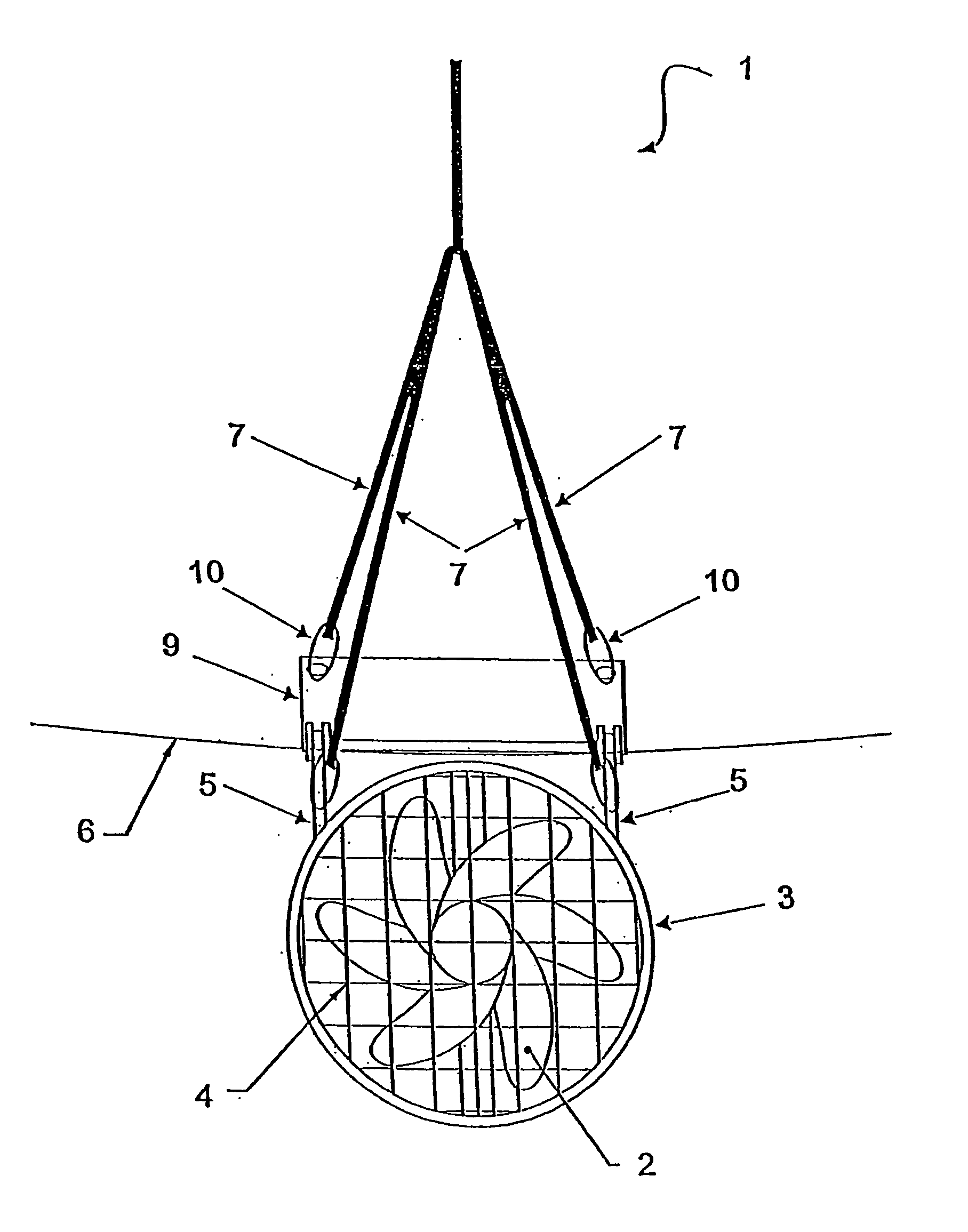
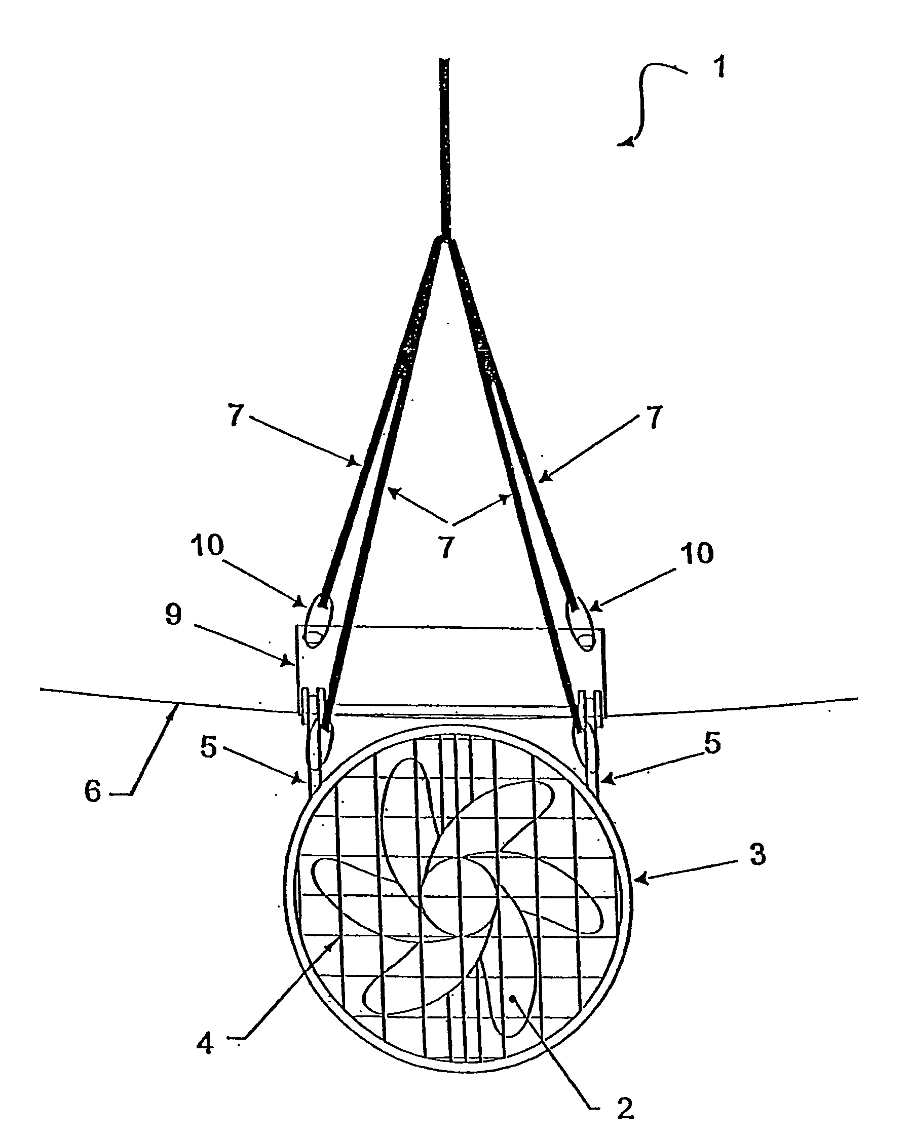
[0073] With reference to the figures there is illustrated a bow thruster generally indicated by arrow 1.

[0074] The bow thruster 1 consists of a bi-directional engine 2 housed within a moulded case 3.

[0075] The open ends of the moulded case 3 are enclosed by a mesh cover 4 in order to protect other water users from inadvertently coming in contact with the engine 2 and also to stop any detritus entering the moulded case 3 and damaging the engine 2.

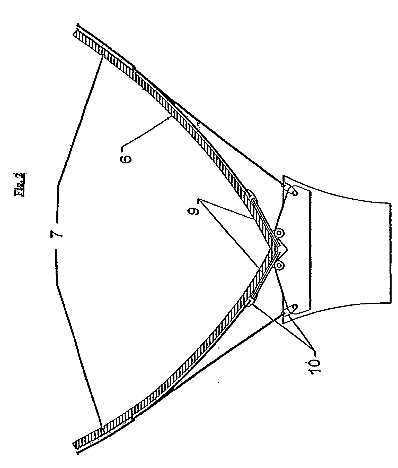
[0076] The moulded case 3 has an upper portion constructed as a cradle 5 which is connected to a set of pivoting plates 9 which automatically adjust so that they easily and snugly fit onto the lower portion of the hull 6.

[0077] Having been lowered into the water the engine 1 is drawn up using a set of halyard ropes 7 until the pivoting plates 9 comes into contact with the lower portion of the hull 6.

[0078] The halyard ropes 7 are then placed under adequate tension so that the engine 1 will remain securely in position transversely across...


PUM


Abstract

A submersible manoeuvring device (1) or manoeuvring a water vessel (6), including a motor device (2), characterised in that the manoeuvring device (1) includes a cradle to which connecting devices (7) can be attached in order to enable the device (1) to be lowered into an operational position with respect to the water vessel and subsequently removed therefrom.

Description

TECHNICAL FIELD [0001] This invention relates to a submersible manoeuvring device. [0002] Reference throughout this specification shall now be made to use of the present invention in relation to operating as a bow thruster to aid the manoeuvring of watercraft during docking. [0003] It should be appreciated however that this should not be seen to be a limitation on the present invention in any way as the present invention may be used to manoeuvre the bow of a watercraft at any other time, or may even be turned roughly through 90° in order that it can be used as a form of propulsion unit. [0004] It is envisaged that this mode of operation would primarily be used to assist boats whose normal propulsion system have become disabled but it can also be fitted to a watercraft without any form of propulsion so that this watercraft is capable of a level of propulsion. BACKGROUND ART [0005] The manoeuvring of watercraft with any level of precision when trying to enter or exit the dock at slow ...

Claims


Application Information

Patent Timeline
Patent Type & Authority Applications(United States)
IPC IPC(8): B63H25/42
CPCB63H25/42B63H2025/425
Inventor MCGARRY, NICHOLAS
Owner MCGARRY NICHOLAS
Learn More