
Active in-fiber optic components powered by in-fiber light

a technology of in-fiber light and active fiber, applied in the direction of liquid/fluent solid measurement, instruments, machines/engines, etc., can solve the problem of leakage of at least a portion of the power light at the junction point, and achieve the effect of being cheap to manufactur

Active Publication Date: 2005-07-28
UNIVERSITY OF PITTSBURGH
View PDF13 Cites 45 Cited by
  • Summary
  • Abstract
  • Description
  • Claims
  • Application Information

AI Technical Summary

Benefits of technology

[0019] It is a further object of this invention to provide a mechanism for powering and tuning in-fiber optic components that eliminates any additional electrical cabling.
[0021] It is still a further object of this invention to provide an optical fiber system that is relatively lightweight.

Problems solved by technology

The diameter of the second core is greater than the diameter of the first core, resulting in leakage of at least a portion of the power light at the junction point.

Method used


Image

  • Active in-fiber optic components powered by in-fiber light
  • Active in-fiber optic components powered by in-fiber light
  • Active in-fiber optic components powered by in-fiber light

Examples


Embodiment Construction

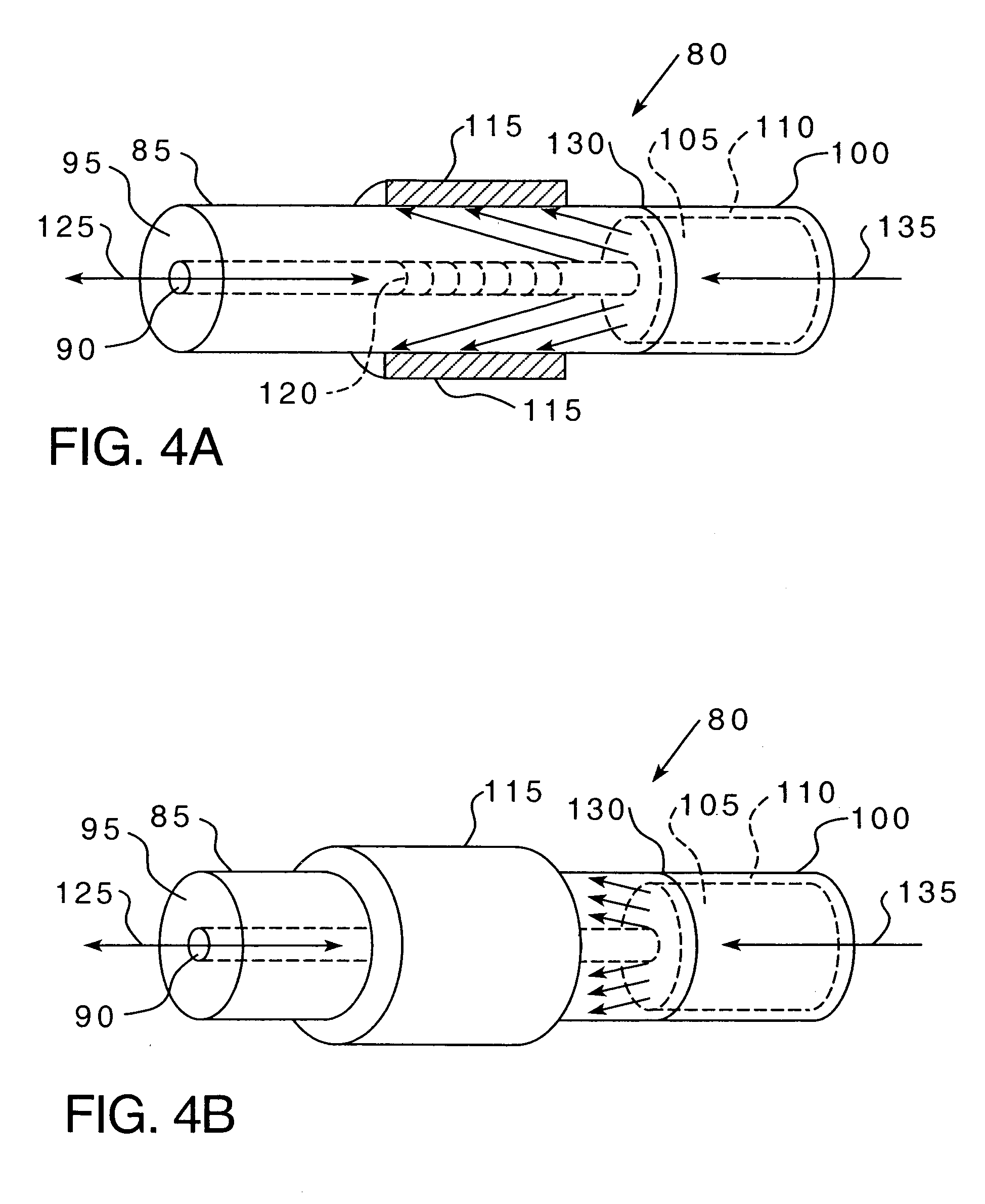
[0049] The present invention relates to various systems and methods for providing active in-fiber optic components that are powered by in-fiber light. Specifically, as described in greater detail herein, various optical fibers are provided that propagate both a sensing or signal light and a power light wherein the power light is used to provide the energy required to tune the in-fiber optic component.

[0050]FIGS. 2A and 2B are side views (2A in partial cross-section) and FIG. 3 is a cross-sectional end view of optical fiber 30 according to one embodiment of the present invention. As seen most readily in FIG. 3, optical fiber 30 includes a core 35, inner cladding 40, outer cladding 45 and protective layer 50. Preferably, core 35, inner cladding 40 and outer cladding 45 are made of light propagating materials, wherein core 35 has an index of refraction that is greater than the index of refraction of inner cladding 40, which in turn is greater than the index of refraction of outer clad...


PUM


Abstract

An optical fiber system that includes an in-fiber optic component powered by in-fiber light includes an optical fiber having a core, wherein the optical fiber propagates a sensing / signal light and a power light, with the sensing / signal light being propagated in the core. An optical transducing element, such as a layer of light absorbing material, is located in proximity to the in-fiber optic component. An optical tap region is provided in the optical fiber in proximity to the optical transducing element, and enables the power light to leak from the optical fiber and be absorbed by the optical transducing element. The optical transducing element converts the absorbed power light into a second energy form, such as heat, which is used to tune the in-fiber optic component.

Description

CROSS-REFERENCE TO RELATED APPLICATION [0001] This application claims the benefit of U.S. Provisional Application No. 60 / 538,708 entitled “Active Fiber Powered by In-Fiber Light,” which was filed on Jan. 23, 2004 and U.S. Provisional Application No. 60 / 559,124 entitled “Active Fiber Optical Components Powered by Light,” which was filed on Apr. 2, 2004.BACKGROUND OF THE INVENTION [0002] 1. Field of the Invention [0003] The present invention relates to fiber optic components used in applications such as fiber optic communications and sensing, and more specifically to active in-fiber optic components that are powered by in-fiber light. [0004] 2. Description of Related Art [0005] Fiber optic components, such as, without limitation, Fiber Bragg Gratings (FBGs), fiber interferometers, and Fabry-Perot cavities (FPs) are well known and are key components used in many optical communication and sensing applications. For example, such components are often utilized in constructing multiplexers ...

Claims


Application Information

Patent Timeline
Patent Type & Authority Applications(United States)
IPC IPC(8): G01F1/688G01F23/292G02B6/02G02B6/14G02B6/34
CPCG01F1/6884G01F23/2925G02B6/29317G02B6/02204G02B6/14G01F23/2927
Inventor CHEN, PENG
Owner UNIVERSITY OF PITTSBURGH
Learn More