
Automated robotic measuring system

Active Publication Date: 2005-07-14
HEXAGON METROLOGY INC
View PDF43 Cites 70 Cited by
  • Summary
  • Abstract
  • Description
  • Claims
  • Application Information

AI Technical Summary

Benefits of technology

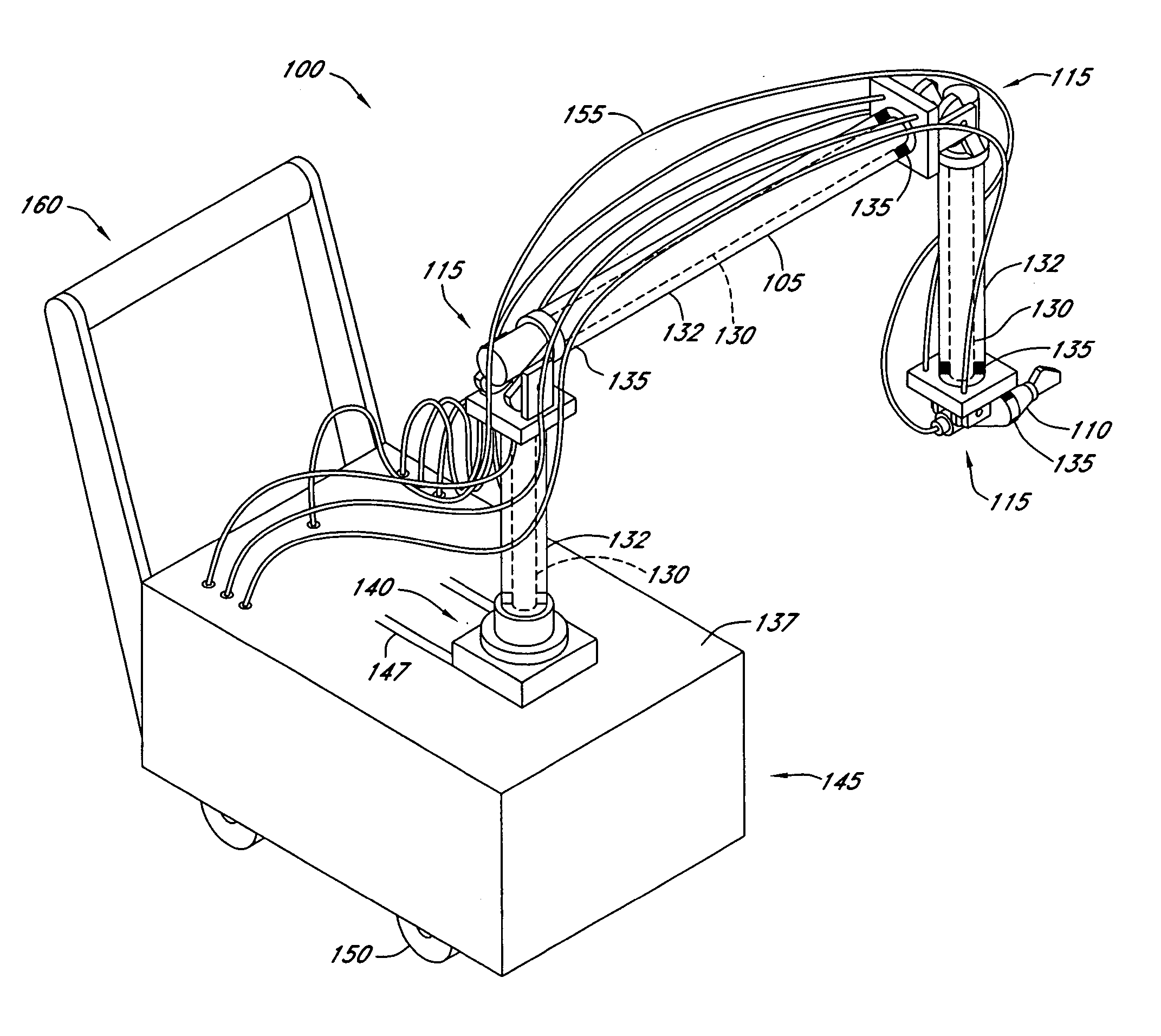
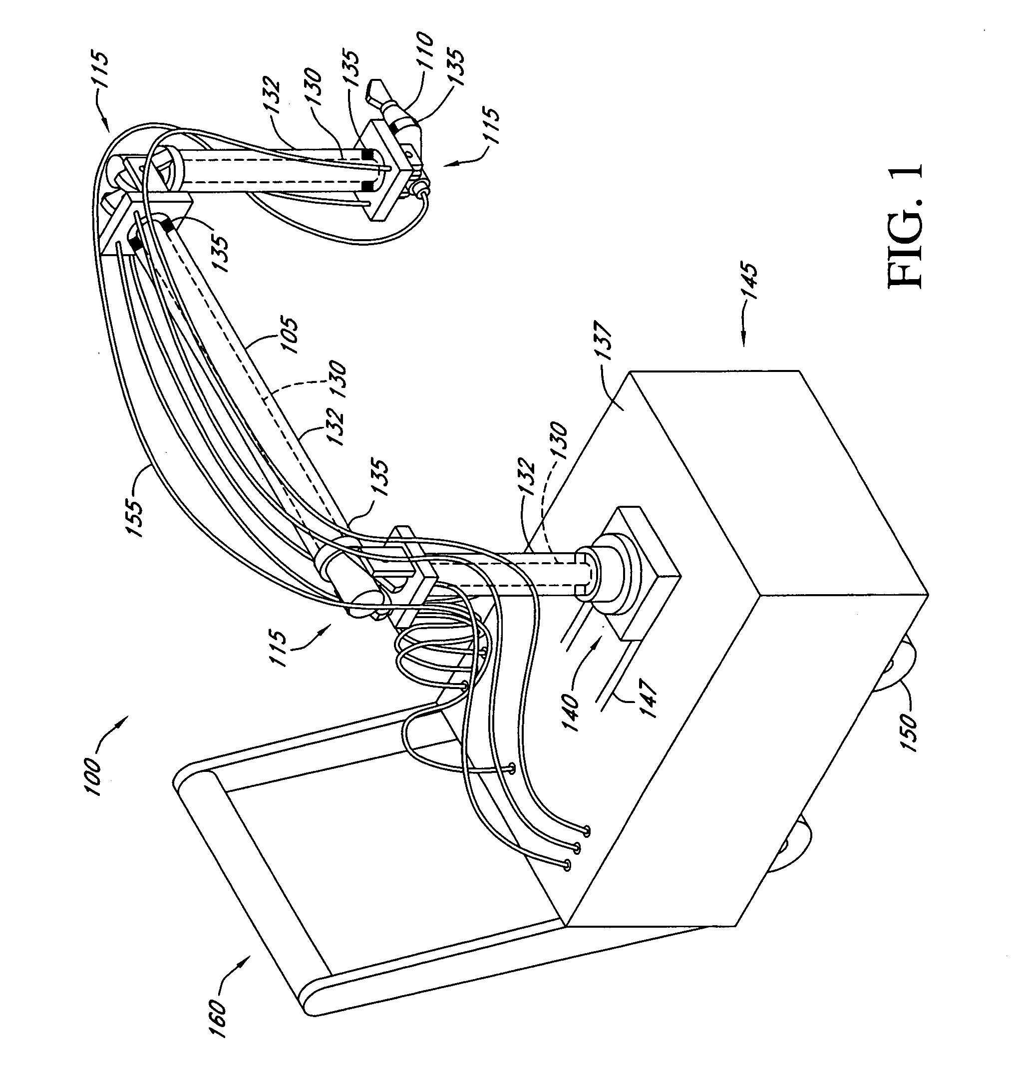
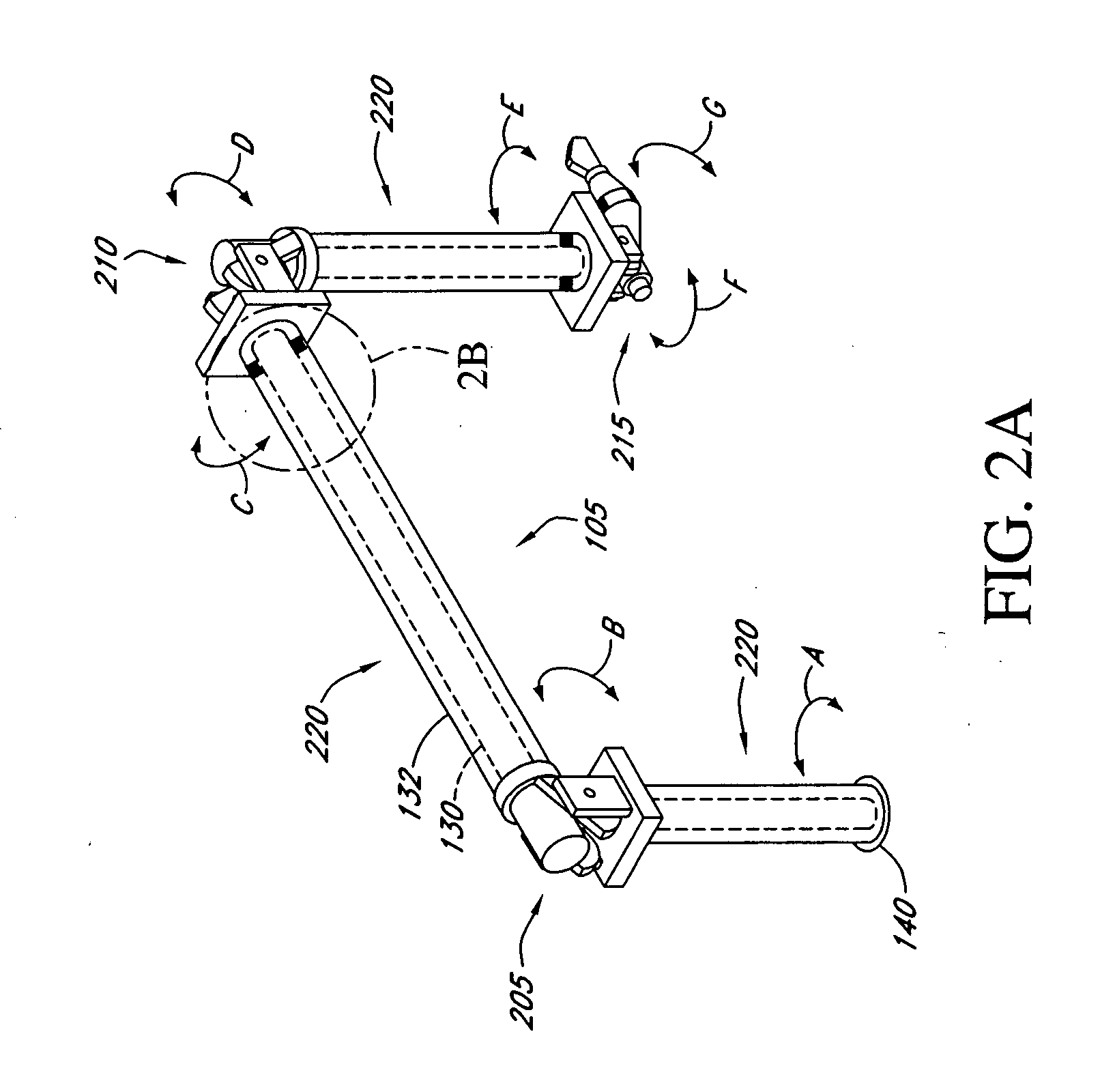
[0010] The present teachings relate to an articulated arm coordinate measuring machine (CMM) having improved tolerance to external physical perturbations. In various embodiments, the CMM comprises a measuring arm having a coordinate acquisition probe or remote scanning device attached thereto coupled with a powered exoskeletal frame and other components that provide improved vibration and temperature damping characteristics over conventional designs.
[0011] In one aspect, the exoskeletal frame and other components that make up the apparatus for actuator assisted movement of the measuring arm may be adapted for use with existing CMM's thus providing a means to improve the performance of these devices. In another aspect, the present teachings describe a configuration for a CMM capable of robotic or motor-assisted movement. Actuators provide movement for the measuring arm and may be remotely located at various positions on the measuring arm or separately contained in an external housing to improve stability and coordinate acquisition accuracy. In certain embodiments, the actuators remotely drive selected hinge, joint, or measuring armature segments using flexible drive cables which enable multi-axis control and movement of the measuring arm, probe, and / or remote scanning device.
[0013] In another aspect, the present teachings describe a system for calibrating and training a CMM. Calibration may be performed in a substantially automated manner or alternatively an operator-assisted mode may be used. Once a training parameter set has been developed, this information may be applied to other similar CMMs improving the efficiency of device calibration or substantially eliminating this process altogether.
[0014] In other embodiments, the present teachings describe a process for determining the position of the measuring arm using encoders which detect the angular position of both the measuring arm and the exoskeletal frame relative to one another. Actuator positioning information stored in a lookup table in combination with encoder determined angular values provides a highly accurate database for aligning the measuring arm and providing feedback to correct / adjust the position of the measuring arm.
[0017] In still other embodiments, the invention comprises a method for positioning an articulated measuring arm. The positioning method further comprises supporting said arm at a plurality of locations with compliant members to reduce mechanical stress on said arm.

Problems solved by technology

One limitation of many conventional instruments is that they are generally sensitive to external physical perturbations including vibrations and fluctuations in temperature which may degrade the accuracy of coordinate acquisition.
In articulated measuring arms, the components that make up the arm segments and hinged portions of the measuring arm are particularly susceptible to localized thermal effects affecting the performance of the instrument and can impart undesirable distortions and inaccuracies in coordinate acquisition.
Additionally, imperfections in hinge, actuator, and motor design can result in a certain degree of variability or “slop” in measuring arm movement further affecting the overall instrument accuracy.
Another problem with existing designs is that inadvertent jarring of the instrument by an operator or other vibrations may result in degradation of coordination acquisition performance.
Despite these considerations it is not uncommon for an instrument to require realignment or recalibration during routine operation thus increasing the time required to obtain a complete coordinate set for a selected object.
For the aforementioned reasons of environmental sensitivity as well as the generally large overall size, weight, and complexity of the instrument itself, conventional instruments are also not well suited for adaptation to portable platforms which include motor-assisted measuring arm articulation or robotic control.

Method used


Image

  • Automated robotic measuring system
  • Automated robotic measuring system
  • Automated robotic measuring system

Examples


Embodiment Construction

[0030] The following detailed description presents various descriptions of certain embodiments of the present teachings described herein. However, the inventive scope of the present teachings can be embodied in a multiplicity of different ways as defined and covered by the claims. In this description, reference is made to the drawings wherein like parts are designated with like numerals throughout.

[0031] While various embodiments of the present teachings are directed towards an automated robotic measuring system or a motor-assisted coordinate measuring machine; one skilled in the technology will appreciate that the systems and methods described herein may be adapted for use with other types of CMMs and PCMMs. For example, the vibration damping and thermal compensation features may be adapted for use with conventional designs to improve their resistance to external perturbations. Similarly, the motor-assisted control and movement characteristics of the present teachings may be adapt...


PUM


Abstract

An automated coordinate measuring system comprising a measuring arm used for acquisition of geometry data that incorporates an exoskeletal structure resilient to physical perturbations including thermal changes and vibrations which may affect coordinate data acquisition. The system may be adapted to a portable platform allowing for convenient positioning and alignment of the measuring arm in a wide variety of environments.

Description

RELATED APPLICATIONS [0001] This application incorporates by reference in its entirety the following co-pending application: attorney docket number ROMINC.003A entitled “TRANSPROJECTION OF GEOMETRY DATA”. BACKGROUND [0002] 1. Field of the Invention [0003] The present teachings generally relate to rectilinear measuring systems and articulated arm coordinate measuring machines and more particularly to a system for automated measuring arm positioning. [0004] 2. Description of the Related Art [0005] Rectilinear measuring systems, also referred to as coordinate measuring machines (CMM's) and articulated arm measuring machines including portable coordinate measuring machines (PCMM's) have been described for generating geometry information from various objects and areas. In general, these instruments capture the structural characteristics of an object for use in electronic rendering and duplication. One example of a conventional apparatus used for coordinate data acquisition comprises a su...

Claims


Application Information

Patent Timeline
IPC IPC(8): G01B5/004G01B5/008
CPCY10T74/20329G01B5/004
Inventor EATON, HOMER
Owner HEXAGON METROLOGY INC
Learn More