
Matrix band retainer

a technology of retainers and band retainers, applied in the field of matrix band retainers, can solve the problems of dislocation of the configuration of the restored tooth, dental discomfort, infection, etc., and achieve the effect of easy slipping out of position

Active Publication Date: 2005-07-07
DENTSPLY SIRONA INC
View PDF9 Cites 23 Cited by
  • Summary
  • Abstract
  • Description
  • Claims
  • Application Information

AI Technical Summary

Benefits of technology

[0008] Conventional matrix band retainers consist of a rigid, cylindrical wire bent so as to have a generally circular body and one of two generally straight tines extending perpendicularly from each end of the circular body. During use, the tines are spread open and placed in the interproximal spaces between the tooth being repaired

Problems solved by technology

However, if the matrix band is not properly held in place then too much or too little filling material may be deposited into the tooth preparation, thereby distorting the configuration of the restored tooth.
An improper filling can lead to dental discomfort, capture of food particles, infections, and other dental problems.
It is desirable, however, to avoid this process because it increases the time and cost of performing the filling procedure and can create anxiety and discomfort for the patient.
One inherent problem with the use of matrix bands and dental wedges, however, is that they are susceptible to moving and slipping out from between the teeth.
One problem with such matrix band retainers is that the tines do not anatomically conform to the shape of the teeth.
This results in inadequate retention of the matrix band such that the matrix band in an anatomically correct conformation.
In addition, some matrix band retainers can easily slip out of position.

Method used


Image

  • Matrix band retainer
  • Matrix band retainer
  • Matrix band retainer

Examples


Embodiment Construction

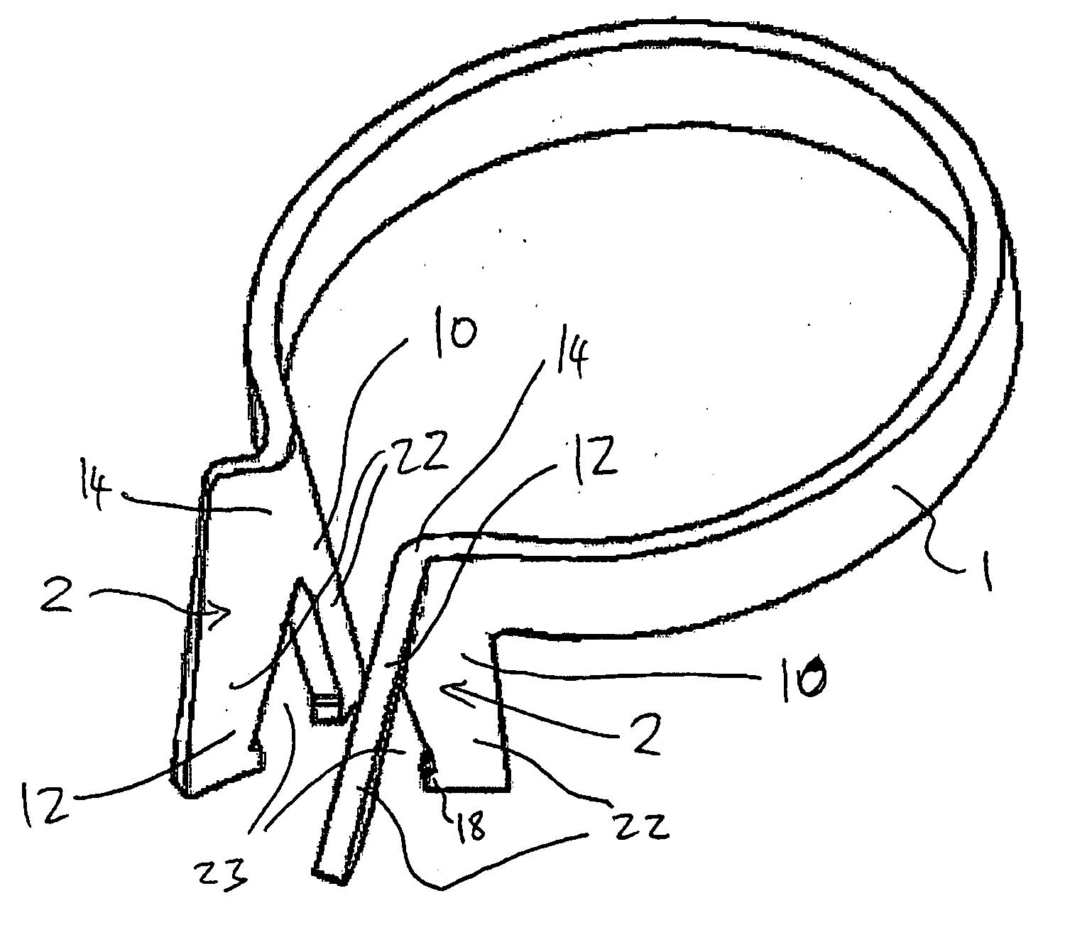
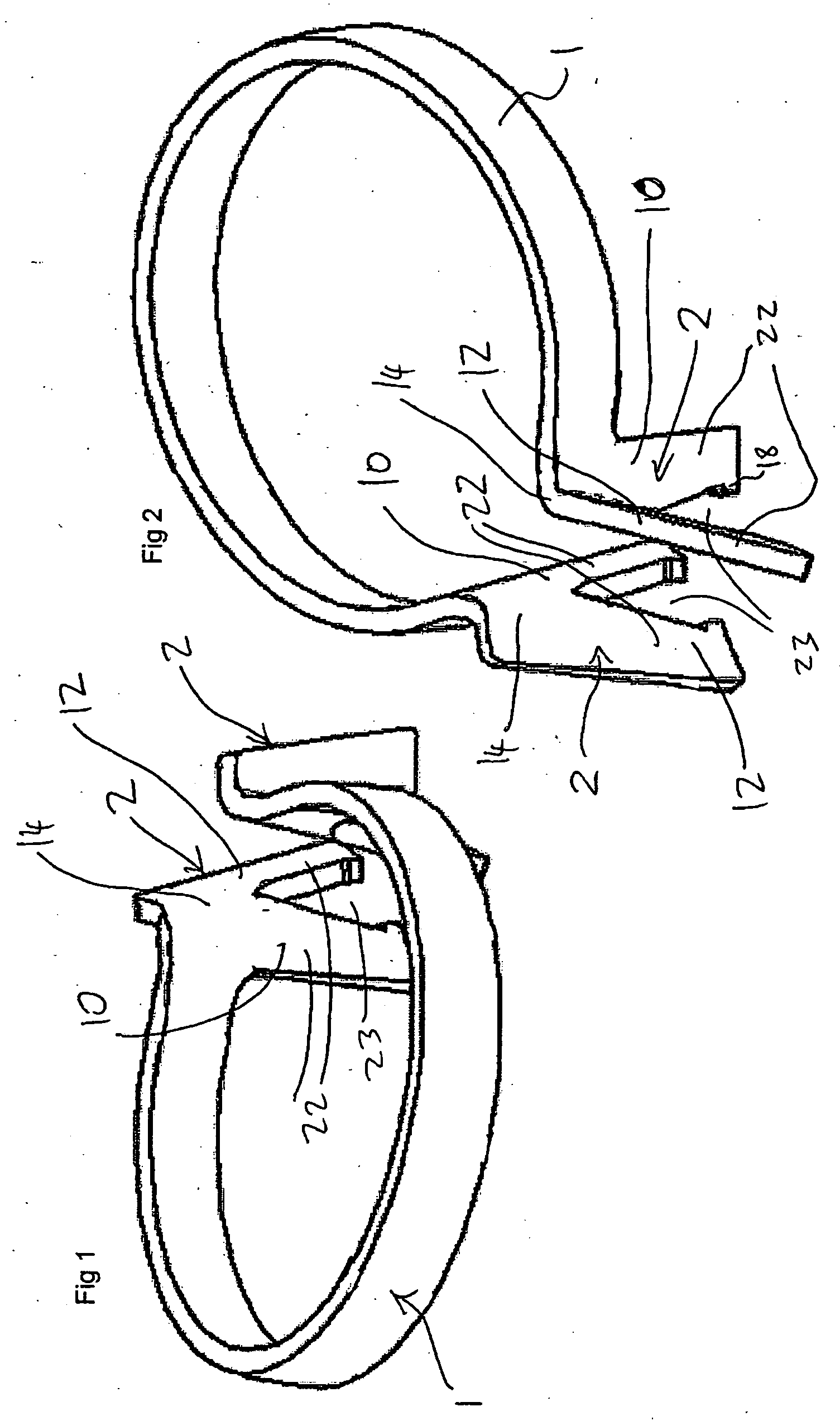
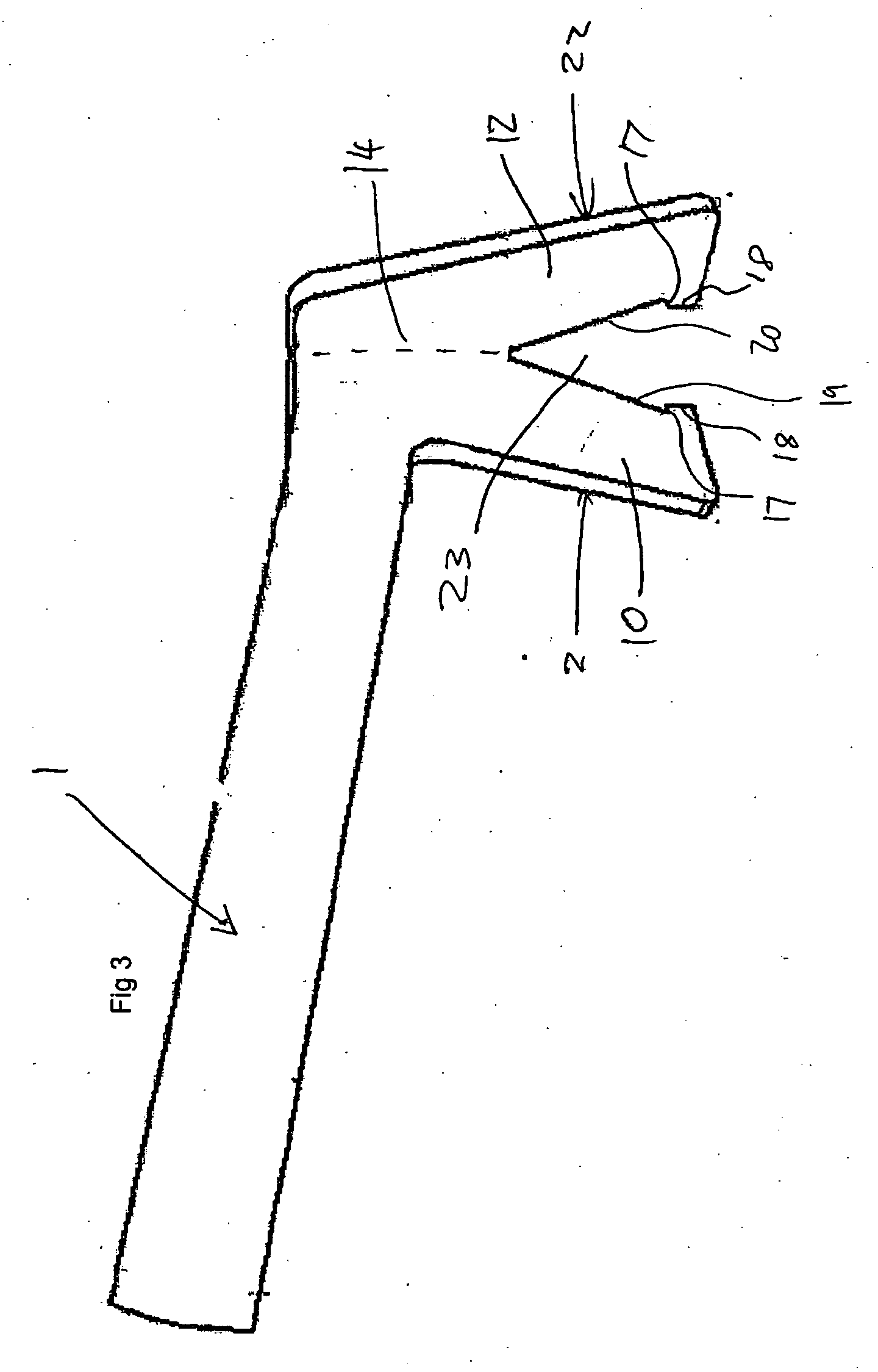
[0031] It is an object of this invention to enable a dentist to more easily restore a proximal cavity on a tooth using a matrix band. The device according to the present invention is a matrix band retainer formed of a planar spring material with two faces on each tine. The faces transmit the force of the spring to separate the teeth while holding the sectional matrix in place. Preferably a gap between the faces of each tine facilitates the easy placement of a dental wedge.

[0032] Referring to the figures in the preferred embodiment of the present invention the matrix band retainer has a main body of an entirely unitary construction with a circular or overall horseshoe shaped spring 1 with a tine 2 at each end. The spring 1 is essentially an open ring. It does not necessarily follow a circular, oval or horseshoe path. Other curvilinear forms could be used. However a substantially circular or horseshoe ring is preferred for providing a combination of open access to the tooth biting su...


PUM


Abstract

A matrix band retainer for dental restoration has a unitary member of a stiff planar spring material. The unitary member has an open ring substantially in a first plane, with the plane of the material of the ring perpendicular to the first plane. A tine at each end of the open ring extends substantially normal to the plane of the ring. Each tine has a first planar portion extending from the ring and a second planar portion extending from the first planar portion. The second planar portion is at an angle to the first planar portion and adjoins the first planar portion to define a ridge. The ridges of each tine face each other across a gap. Each tine may be bifurcated at the end distal from the ring so that the distal portion of each of the first planar portion and the second planar portion are divided by a notch. A dental wedge can be inserted through the notch with the matrix band retainer in place.

Description

BACKGROUND TO THE INVENTION [0001] 1. Field of the Invention [0002] The present invention is in the field of matrix band retainers for use in dental procedures. In particular, the present invention relates to matrix band retainers that are configured to clamp into the interproximal spaces between adjacent teeth to hold a matrix band in proper placement during dental filling procedures. [0003] 2. Summary of the Prior Art [0004] In the field of dentistry, dental practitioners often treat patients who have developed cavities in a tooth. In order to treat cavities the dental practitioner removes the infected portion of the tooth and then deposits a filling material such as a composite, a resinous material, or an amalgam into the tooth preparation. [0005] During the dental filling procedure, a matrix band is typically placed against the side of the tooth to approximately define the desired shape of the restored tooth and to keep the filling material from flowing beyond the desired tooth ...

Claims


Application Information

Patent Timeline
IPC IPC(8): A61C5/12
CPCA61C5/125A61C5/85
Inventor MCDONALD, SIMON PAUL
Owner DENTSPLY SIRONA INC
Learn More