Apparatus for visual comparison of infrared images

Inactive Publication Date: 2005-07-07
FAUBION ROBERT CARL
View PDF8 Cites 28 Cited by
  • Summary
  • Abstract
  • Description
  • Claims
  • Application Information

AI Technical Summary

Benefits of technology

[0014] One advantage of the present invention is the visual presentation of a thermal image, not merely a measurement value of the gross or average temperature of the objects within the field of view. An image permits the user to perceive the objects and distinguish any temperature differences between objects within the field of view. For example, the visual image may portray the brakes, rim, and tire of the vehicle each having a distinct thermal image. Consequently, the user can distinguish which objects within the field of view are relatively hot or cold thereby indicating whether operation of the components is normal.

Problems solved by technology

For example, a prior art device focused at a wheel and brake assembly would be incapable of determining if the tire or the brake was overheating.
None of the devices of the aforementioned patents are capable of determining a radiation imbalance nor are they capable of creating and displaying a thermal image on a visual display apparatus.

Method used


Image

  • Apparatus for visual comparison of infrared images
  • Apparatus for visual comparison of infrared images
  • Apparatus for visual comparison of infrared images

Examples


Embodiment Construction

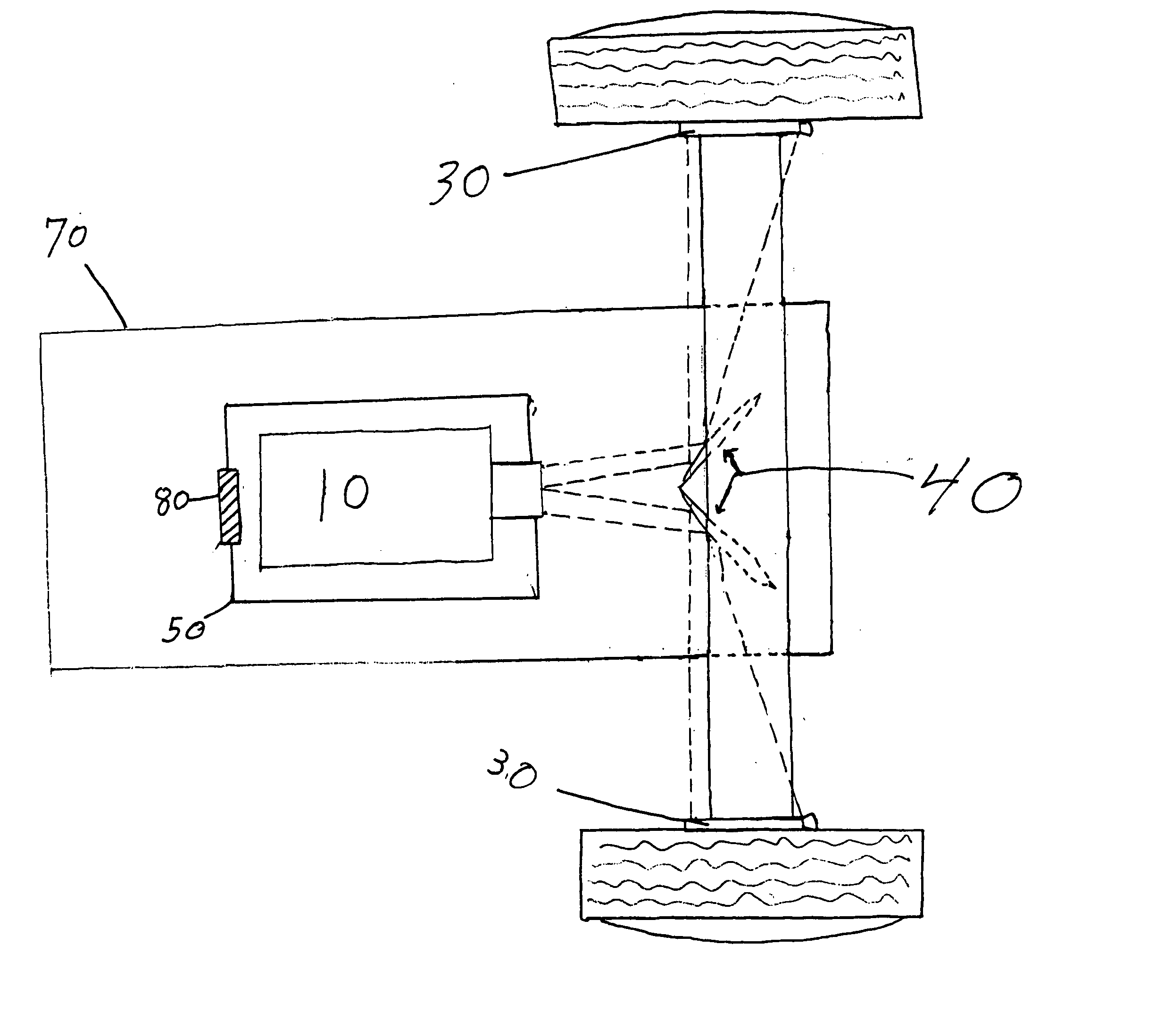
[0026] One preferred embodiment of the present invention is directed to an apparatus for visually displaying an infrared image of a plurality of vehicular components in a composite view. More particularly, the present invention is directed to the use of a single infrared camera for obtaining thermal images of a brake and other undercarriage components of a vehicle.

[0027] The term “vehicle” as used throughout the specification and claims is not limited simply to powered vehicles. Vehicles can include but are not limited to cars, trucks, semi-trucks, trailers having two or more wheels, and heavy equipment such as tractors, backhoes, etc. It may also include railway cars or other vehicles that move on tracks. The term “vehicular components” as used throughout the specification and claims is intended to mean any device, apparatus, or assembly connected to a vehicle. Such vehicular components may, but need not, be integral to the vehicle itself and can include but are not limited to bra...


PUM


Abstract

A method and apparatus for visually observing thermal disparities between like vehicular components that are spatially separated. The invention uses only one infrared camera and one or more surfaces to reflect the thermal image of spatially separated components into the camera. The image generated by the infrared camera can be sent directly to a viewing apparatus or to a computer capable of controlling internal camera functions as well and providing video processing and analysis capabilities.

Description

BACKGROUND OF THE INVENTION [0001] 1. Field of the Invention (Technical Field) [0002] The present invention relates to thermography. More particularly, the present invention relates to a method and apparatus for displaying more than one infrared image to permit visual comparison of objects within the field of view of the apparatus. [0003] 2. Description of Related Art [0004] Note that the following discussion refers to a number of publications by authors and year of publication, and that due to recent publication dates certain publications are not to be considered as prior art vis-a-vis the present invention. Discussion of such publications herein is given for more complete background and is not to be construed as an admission that such publications are prior art for patentability determination purposes. [0005] Motor vehicle brake components play an essential role in contributing to safety on our nations highways. As such, several inventions have been developed to detect cold brake ...

Claims


Application Information

Patent Timeline
IPC IPC(8): B60T17/22B61K9/06G01J5/08
CPCB60T17/22B61K9/06G01J5/0893G01J5/0809G01J5/089G01J5/08G01J5/0808G01J5/07
Inventor FAUBION, ROBERT CARL
Owner FAUBION ROBERT CARL
Why Eureka
Try Eureka