
Hybrid composite-metal energy absorbing seat

a composite metal and energy-absorbing technology, applied in the direction of chairs, pedestrian/occupant safety arrangements, aircraft ejection means, etc., can solve the problems of insufficient design data relating to crash/high-speed deformation environments, difficult to form complex geometry, and excessive assembly time and increased costs

Inactive Publication Date: 2005-07-07
TRITON AEROSPACE
View PDF0 Cites 15 Cited by
  • Summary
  • Abstract
  • Description
  • Claims
  • Application Information

AI Technical Summary

Benefits of technology

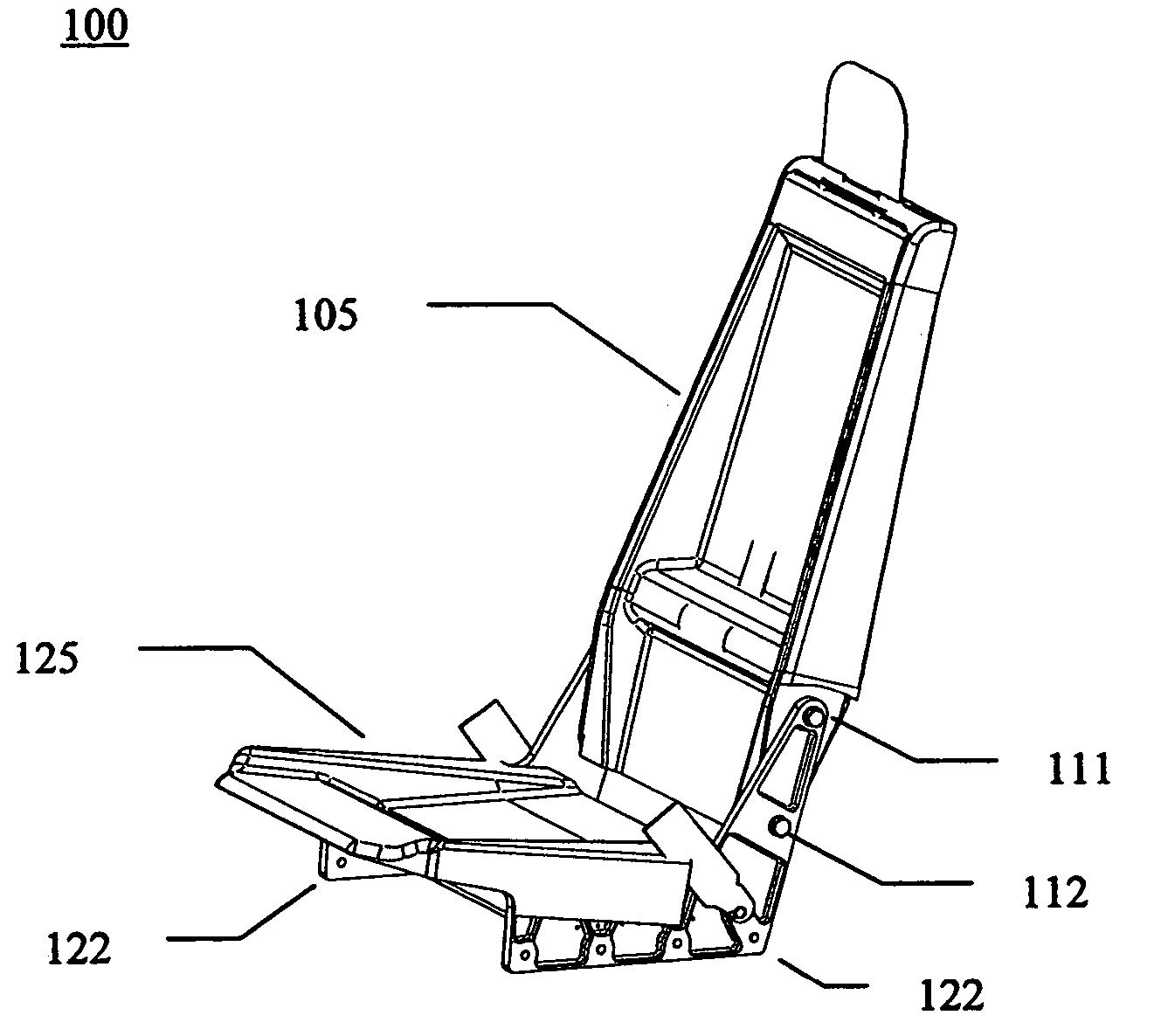
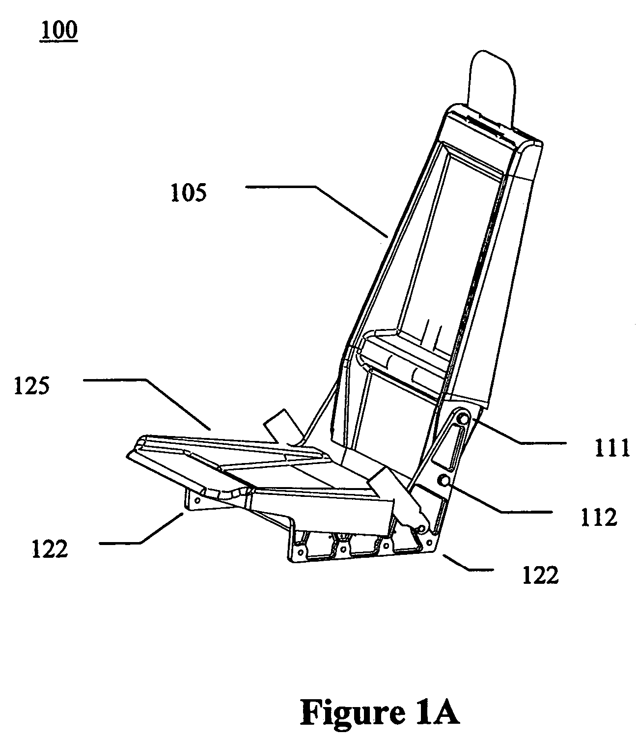
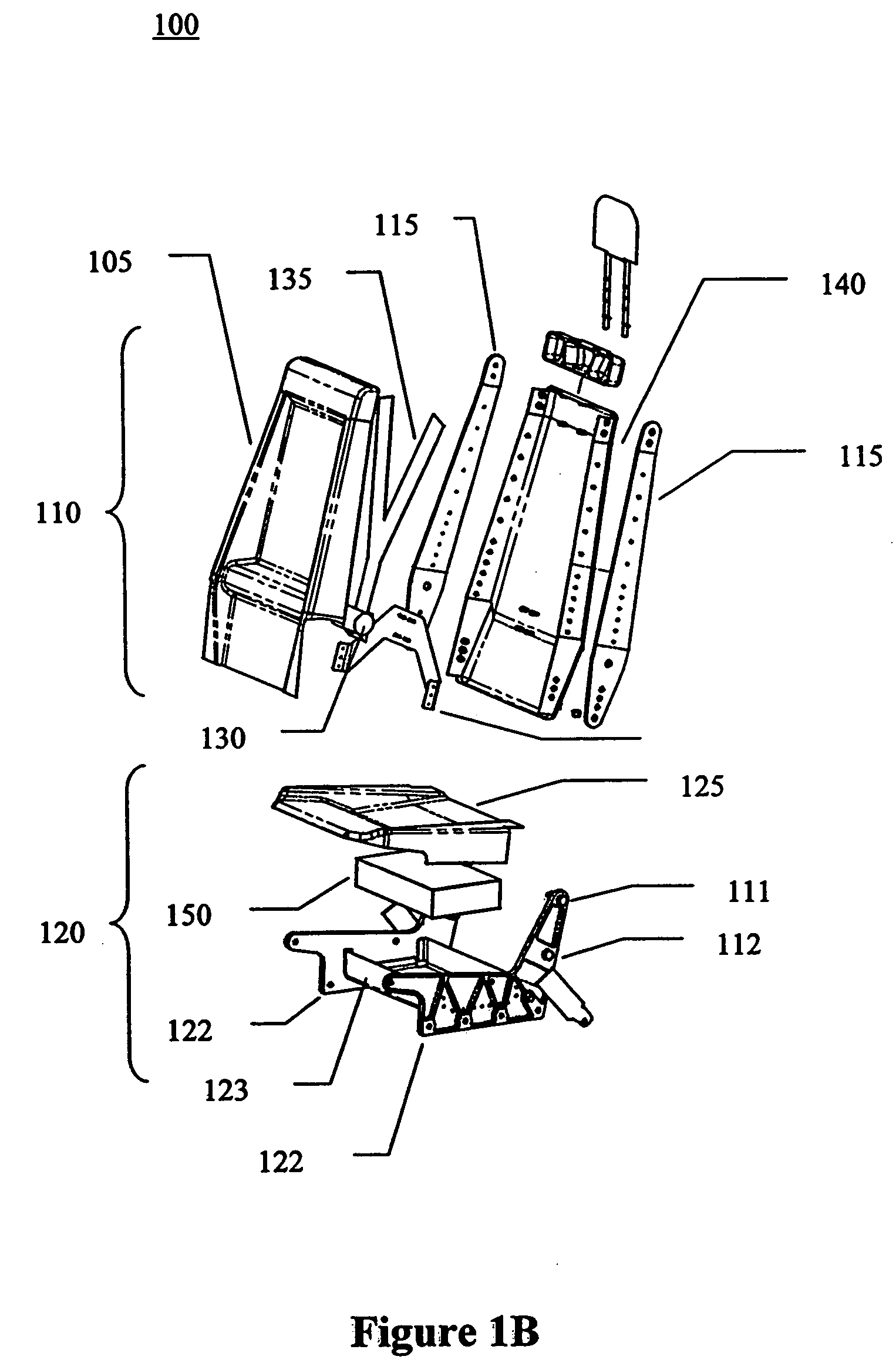
The present invention provides an improved seat for aircraft applications that includes a force dissipation assembly. The seat is made of a seat base assembly and a seat back assembly. The seat base assembly includes metal frame elements joined by a seat pan assembly and covered with a seat pan cover, which serves as an energy absorbing element to absorb severe downward crash load energy. The seat back assembly includes metal frame elements joined by a contoured composite seat back, which absorbs forward crash load energy by permanently deforming during a severe forward crash load. The design of the seat provides flexibility in both design and aesthetics.

Problems solved by technology

Conventional aluminum seats have numerous expensive small components, which contribute to excessive assembly time and increased cost.
In addition, it is often difficult to form the complex geometry that might be preferred for interior styling.
Although composite seats are less expensive to assemble and can be used to form complex shapes, there is insufficient design data relating to crash / high-speed deformation environments.
Also contributing to the inavailability of crash test data is that fact that composites don't plastically deform—thus making crash reaction calculations difficult.

Method used


Image

  • Hybrid composite-metal energy absorbing seat
  • Hybrid composite-metal energy absorbing seat
  • Hybrid composite-metal energy absorbing seat

Examples


Embodiment Construction

[0024] A cost effective hybrid composite-metal energy absorbing aircraft seat is described that provides a strong, lightweight structure for enhanced occupant safety. Broadly stated, embodiments of the present invention seek to achieve an appropriate combination of composite and metal parts in a way that meets current FAR Part 23 requirements while reducing part count, part cost and assembly cost to provide an affordable aircraft seat.

[0025] Embodiments of the present invention also seek to provide a seat which includes a portion having a deformable core, and wherein the seat further includes an assembly which engages the deformable core during a mishap, or crash, thereby further dissipating some of the force of the crash.

[0026] Embodiments of the present invention may be manufactured as original equipment, or alternatively may be manufactured in the nature of a retrofit. A goal of various embodiments of the present invention is to provide a seat which is relatively simple in desi...


PUM

PropertyMeasurementUnit
temperatureaaaaaaaaaa
crash energyaaaaaaaaaa
energyaaaaaaaaaa

Abstract

A hybrid composite-metal energy absorbing seat is described. According to one embodiment, an aircraft seat includes a seat base assembly and a seat back assembly. The seat base assembly includes multiple rigid metal seat base side frame elements joined by a lower seat pan, an energy absorbing element placed on the lower seat pan to deform and absorb downward energy in a crash, and a contoured seat pan whose sides extend past the seat base side frame elements and deform to absorb downward energy in a crash. The seat back assembly is attached to the seat base assembly and includes multiple rigid metal seat back side frame elements joined by a contoured composite seat back. The rigid metal seat back side frame elements absorb forward crash load energy by permanently deforming during a severe forward crash load. The contoured composite seat back provides design / aesthetic flexibility.

Description

[0001] This application claims the benefit of U.S. Provisional Application No. 60 / 373,986, filed Apr. 19, 2002 and U.S. Provisional Application No. 60 / 378,195, filed May 6, 2002; U.S. Utility Patent Application No. 10 / 420,566, all of which are hereby incorporated by reference in their entirety.COPYRIGHT NOTICE [0002] Contained herein is material that is subject to copyright protection. The copyright owner has no objection to the facsimile reproduction of the patent disclosure by any person as it appears in the Patent and Trademark Office patent files or records, but otherwise reserves all rights to the copyright whatsoever. BACKGROUND [0003] 1. Field [0004] Embodiments of the present invention generally relate to a simple, lightweight and affordable seat structure. More particularly, embodiments of the present invention relate to a hybrid composite-metal seat assembly intended for use as an energy absorbing aircraft seat and meeting the current Federal Aviation Regulations (FAR) Par...

Claims


Application Information

Patent Timeline
Patent Type & Authority Applications(United States)
IPC IPC(8): B60N2/42B60N2/427B64D11/06B64D25/04B64D25/10
CPCB60N2/4242B60N2/42709Y02T50/46B64D25/04B64D25/10B64D11/0689Y02T50/40
Inventor KULL, MATTHEW H.OLCOTT, DENNIS D.WILSON, SHARON M.
Owner TRITON AEROSPACE
Learn More