Waste heat recovery system of heat source, with rankine cycle
- Summary
- Abstract
- Description
- Claims
- Application Information
AI Technical Summary
Benefits of technology
Problems solved by technology
Method used
Image
Examples
first embodiment
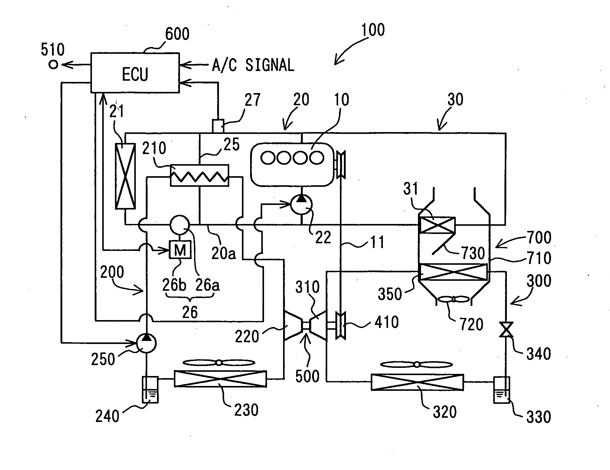
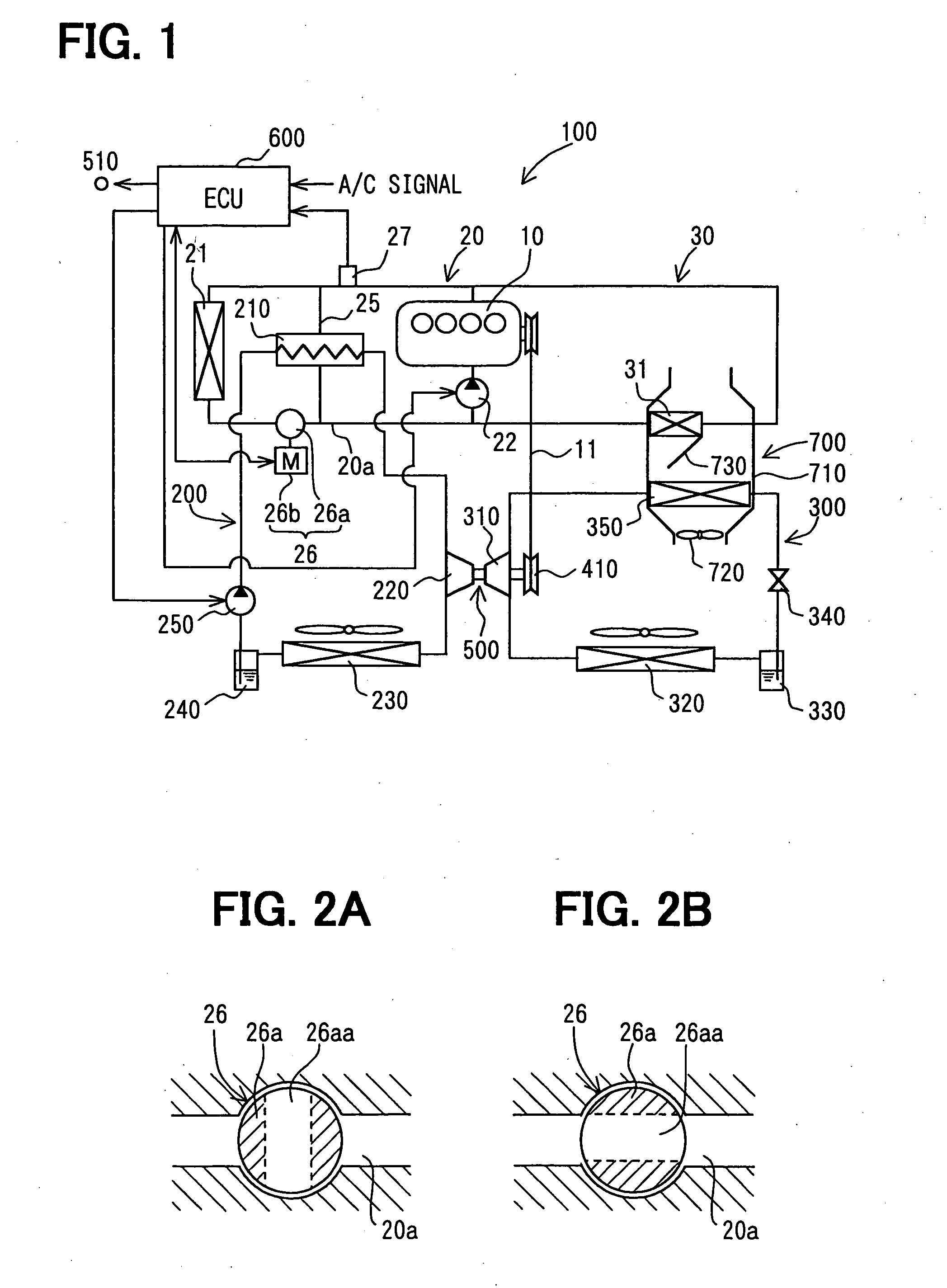
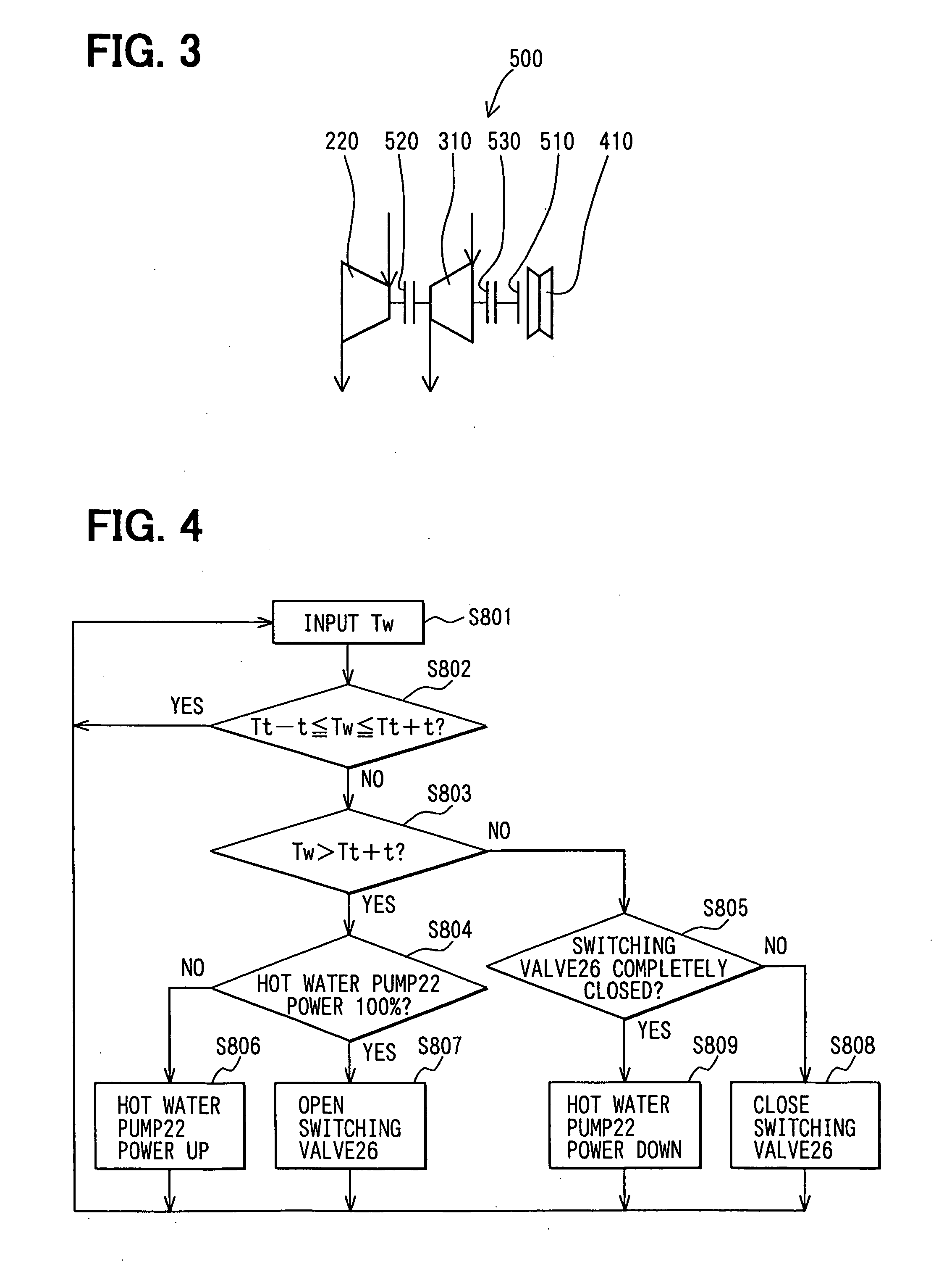
[0039] The first embodiment of the present invention will be now described with reference to FIGS. 1-4. As shown in FIG. 1, a waste heat recovery system 100 for recovering waste heat of an internal combustion engine 10 is constructed with a Rankine cycle 200 and a refrigerant cycle 300.
[0040] The internal combustion engine 10 is a water-cooled engine cooled by circulation of cooling water. The engine 10 includes a circulation path (not shown) inside a cylinder block or the like. The circulation path is located around a combustion chamber (not shown) of the engine 10. Cooling water flows through the circulation path so as to perform a heat transmitting of heat energy from the engine 10 to the cooling water. The heat energy is a part of energy generated by combustion performed in the combustion chamber of the engine 10. The cooling water is heated in the engine 10, circulated in the circulation path of the engine 10, and then cooled in a cooling water circuit 20 including a radiator ...
second embodiment
[0081] The second embodiment of the present invention will be now described with reference to FIGS. 5 and 6.
[0082] A switching valve 126, which has a generally known thermostat, is used in the second embodiment, instead of the electrically driven switching valve 26 described in the first embodiment.
[0083] As shown in FIG. 5, the control unit 600 controls the hot water pump 22, but does not control the switching valve 126, in accordance with the outlet water temperature Tw of the engine 10. The thermostat responds to the temperature of cooling water flowing through the cooling water circuit section 20a, so that the radiator distribution flow amount is controlled by the switching valve 126 from zero to the maximum flow amount.
[0084] The hot water pump 22 is an electrically driven pump. Therefore, a discharge amount (discharge capacity) of the electrically driven hot water pump 22 is not limited due to a rotation speed of the engine 10, compared with a mechanical type pump. The disc...
third embodiment
[0092] The third embodiment of the present invention will be now described with reference to FIGS. 7 and 8.
[0093] As shown in FIG. 7, a hot water pump 122, which has a generally known mechanical structure, is used in the third embodiment, instead of the electrically driven hot water pump 22 described in the first embodiment. Further, the control unit 600 controls the switching valve 26, but does not control the hot water pump 122.
[0094] The switching valve 26 is an electrically driven switching valve. Therefore, the control unit 600 can control the switching valve 26 without delaying, compared with a conventional switching valve using a thermostat which has a relatively slow response control characteristic. The radiator distribution flow amount is controlled at a predetermined flow amount in accordance with the outlet water temperature Tw detected by the water temperature sensor 27, for example.
[0095] Next, the control operation (third control operation) for controlling the flow ...
PUM
 Abstract
Description
Claims
Application Information
 - R&D
- Intellectual Property
- Life Sciences
- Materials
- Tech Scout
- Unparalleled Data Quality
- Higher Quality Content
- 60% Fewer Hallucinations
Browse by: Latest US Patents, China's latest patents, Technical Efficacy Thesaurus, Application Domain, Technology Topic, Popular Technical Reports.
© 2025 PatSnap. All rights reserved.Legal|Privacy policy|Modern Slavery Act Transparency Statement|Sitemap|About US| Contact US: help@patsnap.com


