
Imaging systems for use with patrol cars and patrol cars having such imaging systems

a technology for imaging systems and patrol cars, which is applied in the field of imaging systems for patrol cars and patrol cars having such imaging systems, can solve the problems of difficult to ensure the space for placing the controller, the controller for operating the devices used for the various police services is relatively large, and the camera is not adapted to take up or record image information with regard to the places traveled by the automobile, so as to improve the accuracy of time information corresponding to the image information stored in the memory device, and facilitate the synchronization operation

Inactive Publication Date: 2005-06-23
TIETECH CO LTD
View PDF9 Cites 62 Cited by
  • Summary
  • Abstract
  • Description
  • Claims
  • Application Information

AI Technical Summary

Benefits of technology

[0014] Therefore, the imaging systems can operate in various image-pick up modes in response to the detected condition(s) of the sensor(s). As a result, the operability of the imaging systems may be improved.
[0040] In a still further aspect of the present teachings, the controller has an internal clock. The internal clock functions to synchronize the time of the internal clock with the correct time at predetermined intervals. The controller may automatically conveniently perform the synchronizing operation when an engine of the patrol car is started for example. As a result, the accuracy of the time information corresponding to the image information stored in the memory device can be improved.

Problems solved by technology

In addition, although the camera of the above Japanese publication picks up images of the preceding and succeeding automobile and the location of the white line placed upon the road, the camera is not adapted to take up or record image information with regard to the places traveled to by the automobile.
In general however, the controller for operating the devices used for the various police services has a relatively large size.
Therefore, there has been a problem in that it is difficult to ensure enough space for placing the controller.
However, the overall system typically has a relatively large size and increased introduction costs with this arrangement.

Method used


Image

  • Imaging systems for use with patrol cars and patrol cars having such imaging systems
  • Imaging systems for use with patrol cars and patrol cars having such imaging systems
  • Imaging systems for use with patrol cars and patrol cars having such imaging systems

Examples


first representative embodiment

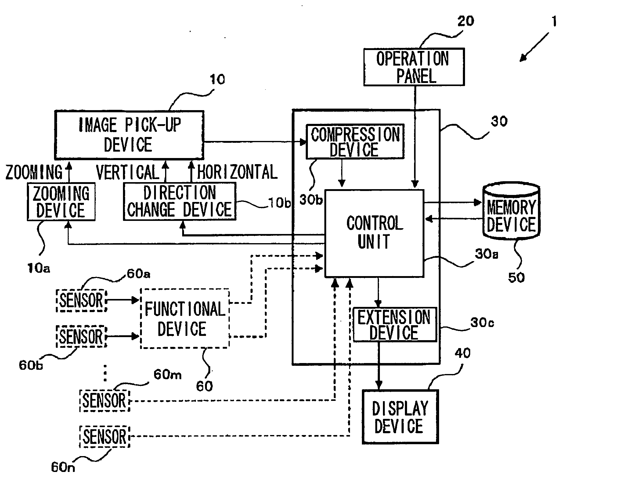
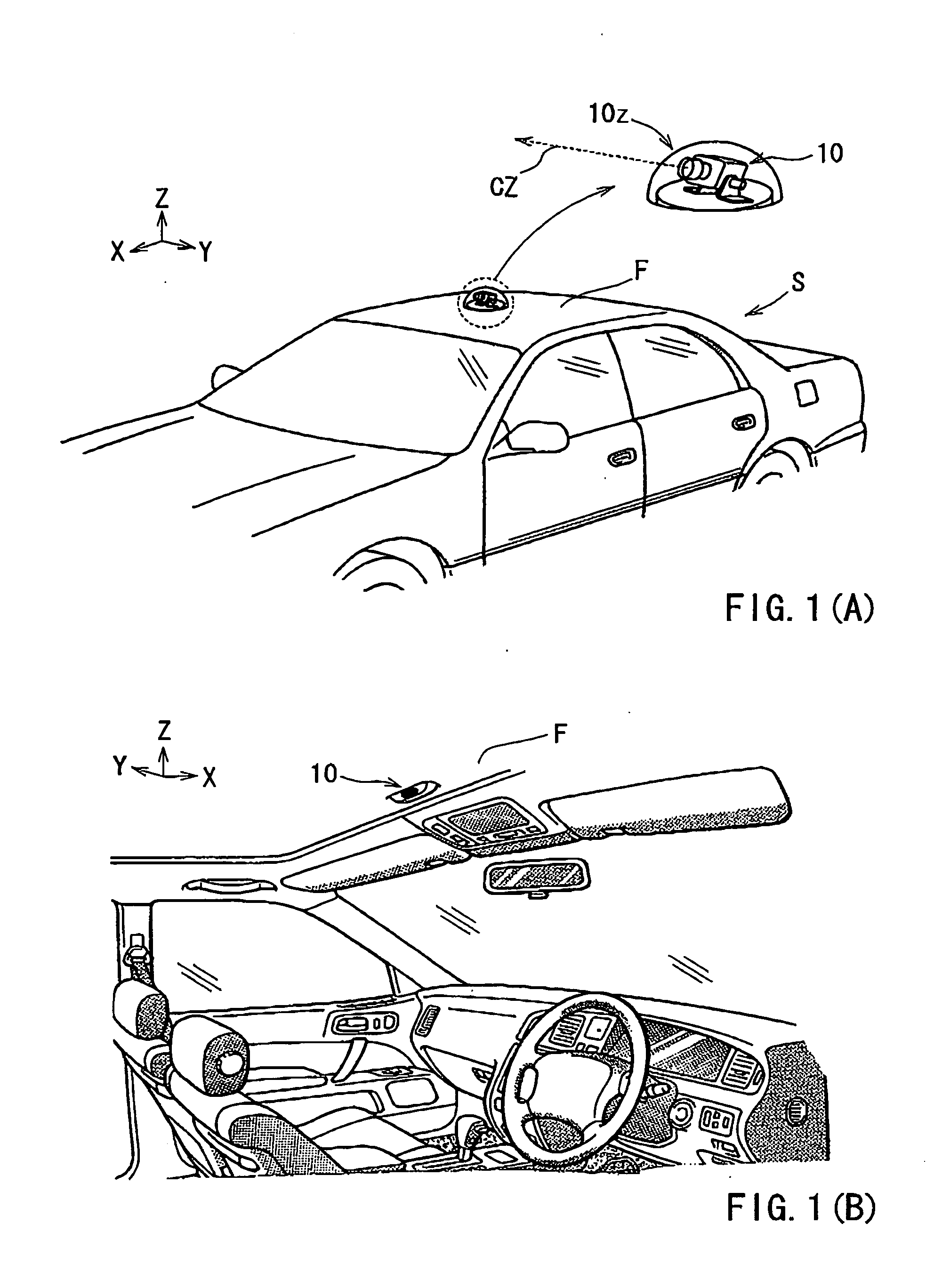
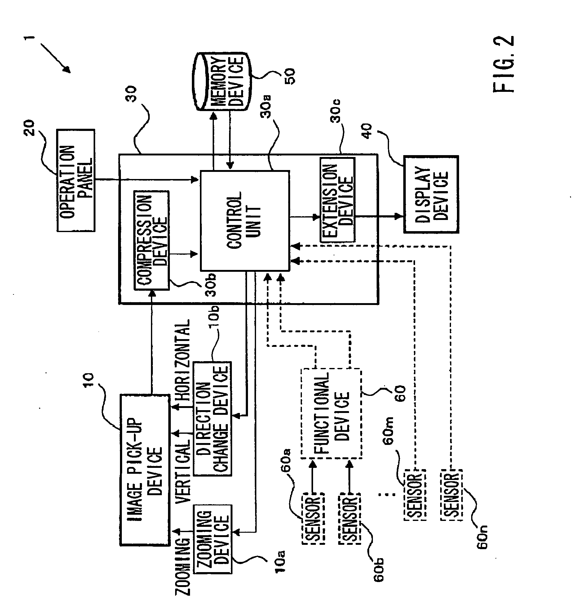
[0058] A first representative embodiment of the present invention will now be described with reference to FIGS. 1(A) and 1(B), and FIGS. 2 and 3. The general construction of the first representative embodiment will be first described with reference to these drawings.

General Construction

[0059] FIGS. 1(A) and 1(B) show different aspects of an image pick-up device 10 of a representative imaging system 1 (see FIG. 2) adapted to be mounted to a patrol car S (a police car in this representative embodiment). In FIG. 1(A), the image pick-up device 10 is mounted to an external surface of a vehicle roof R, in order to capture images of the external environment of the patrol car S. The image pick-up device 10 is covered by a protective cover 10z in order to prevent or minimize the influence of the outside conditions, such as the weather, upon the image pick-up device 10. The image pick-up device 10 has an optical axis CZ. The orientation of the optical axis CZ can be changed with regard to ...

second representative embodiment

[0084] The second representative imaging system is configured to transmit the image information picked up by the image pick-up devices 11a, 11b and 11c, together with the positional information from the positional information acquisition device 13, in the same file for example.

[0085] The image pick-up device 11a is mounted within the patrol car 100 and is positioned to record images of the environment to the front of the patrol car 100, over the windshield (not shown in FIG. 1) of the patrol car 100. Each time the image is picked up by the image pick-up device 11a during a predetermined time, the image is transmitted to a compression device 14a of the control unit 14. The compression device 14a receives the images as image information consisting of a series of continuous frames of still images or a video image. The image pick-up device 11b is also mounted within the patrol car 100. Image pick-up device 11b is positioned to capture images of the environment to the rear of the patrol...

third representative embodiment

[0096] The third representative imaging system differs from the second representative embodiment in that the image information picked up by the image pick-up devices 11a, 11b, and 11c, is transmitted in a separated file apart from the positional information determined by the positional information acquisition device 13 (i.e., GPS). However, the components of the third representative embodiment are substantially the same as those of the second representative embodiment, which were described with reference to FIG. 4. Therefore, the third representative embodiment will be described with respect to only the transmission of the information file.

[0097] Similar to the second representative embodiment, the CPU 14c issues instructions to store the image information in the buffer memory 14f, preferably together with the positional information. The positional information may be stored in another memory device (not shown). In this representative embodiment, as shown in FIG. 6, the positional i...


PUM


Abstract

An imaging system for use with a patrol car includes at least one image pick-up device, a memory device, and a controller. The controller executes instructions to store image information captured by the image pick-up device in the memory device. Various operating modes of the imaging system may be selected based in part upon the operating conditions of the patrol car. Recording and transmitting of the image information may be performed manually or automatically, depending upon the operator of the system and the conditions of the patrol car. Both the interior of the patrol car (i.e., rear seat), and the environment outside of the patrol car (i.e., to the front and rear of the vehicle), may be recorded by the image pick-up systems. Additionally, automatic control such as 360° views upon reaching a desired destination may be performed based upon the configuration of the imaging system.

Description

[0001] This application claims priority to Japanese patent application serial numbers 2003-421014, 2004-44156, and 2004-218764, the contents of which are incorporated herein by reference. BACKGROUND OF THE INVENTION [0002] 1. Field of the Invention [0003] The present invention relates to imaging systems for use with patrol cars and also relates to patrol cars having such imaging systems. [0004] 2. Description of the Related Art [0005] Japanese Laid-Open Patent Publication No. 11-312300 teaches an imaging system adapted to be mounted to an automobile. The imaging system includes a camera mounted on the automobile so that the information required for safe traveling can be collected in response to the traveling speed of the automobile. For example, such information may include the monitoring of the preceding automobile or the succeeding automobile and information with regard to the location of the white line on the road. [0006] In recent years, there has been an increasing demand for p...

Claims


Application Information

Patent Timeline
Patent Type & Authority Applications(United States)
IPC IPC(8): G07C5/00G07C5/08H04N5/225H04N5/232H04N7/18
CPCG07C5/008G07C5/0891H04N5/2251H04N5/232H04N5/23206H04N7/181H04N5/23245H04N5/23248H04N5/23293H04N5/23296H04N5/23241H04N23/667H04N23/68H04N23/69
Inventor NOMURA, TOSHIAKITANAKA, HIROYUKIHATTORI, TETSUYAHOTTA, ATSUSHI
Owner TIETECH CO LTD
Learn More