Plural channel analog-to-digital converter, method and meter employing an input channel with a predetermined direct current bias
an analog-to-digital converter and input channel technology, applied in the field of analog-to-digital converters, can solve problems such as data synchronization and other problems, and achieve the effect of data loss
- Summary
- Abstract
- Description
- Claims
- Application Information
AI Technical Summary
Benefits of technology
Problems solved by technology
Method used
Image
Examples
example 1
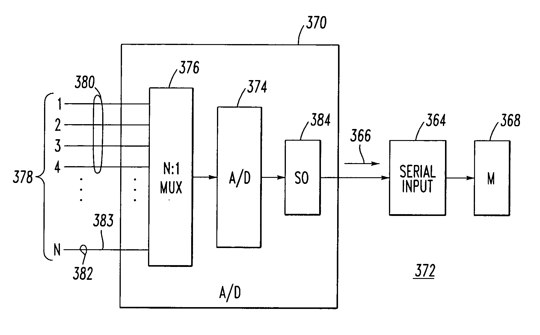
[0042] The AD73360L A / D converter 40′ is a six-input channel, 16-bit, analog front end including six independent encoder channels corresponding to the six analog inputs 140,142,144,146,148,150. As shown following the analog input 140, each of these channels includes a signal conditioner 158, a switched capacitor programmable gain amplifier (PGA) 160, a sigma-delta analog-to-digital (A / D) converter (ADC) 162 and a decimator 164. An on-board digital filter (not shown), which forms part of the sigma-delta ADC 162, also performs critical system-level filtering. Each of the ADCs, such as 162, corresponds to one of the alternating current signals of the first and second input channels 100,102. A serial I / O port 166 receives digital values from the decimators, such as 164, and provides a suitable interface 167 to a processor (not shown) and / or another cascaded A / D converter (not shown).
[0043] The interface 167 includes a RESET input 168, which receives an active low reset signal, in order...
example 2
[0069] For a metering application, one or two of the single AD73360L A / D converter 40′ of FIG. 3 may be employed to measure the voltages and currents in all phases of a plural-phase power supply (not shown). The simultaneous sampling architecture of the converter 40′ is ideal for this application where simultaneous sampling is critical to maintaining the relative phase information between the plural voltage and current phases. For example, two or more A / D channels may be employed to measure the voltages in each phase via the circuit 152 of FIG. 4. Two or more A / D channels may be employed to measure the current flowing in each phase via the circuit 154 of FIG. 8. Alternatively, any suitable current-sensing isolation amplifiers and / or Hall-effect sensors may be employed. In turn, a suitable processor, such as the DSP 88 of FIG. 2, is employed to perform the mathematical calculations on the digital values provided by the A / D converter 40′.
example 3
[0070]FIG. 13 shows an example meter 350 including an A / D converter 352 having 12 channels 354 for a three-phase power line 353. The channels 354 input three phase voltages VA, VB, VC, one neutral voltage VN, three phase currents IA, IB, IC, one neutral current IN, one ground current IG, and three additional phase voltages VAG, VBG, VCG, which are referenced, for example, on the primary side of a transformer (T) 355. All of the channels 354 are associated with alternating current signals having a direct current value of about zero. All but one or two of these channels 354 are part of first channels 44′, which employ biasing and scaling circuits (BSCs) 356,357, which input a corresponding one of the alternating current line voltage signals and the alternating current line current signals, and which output a corresponding analog output. Preferably, one (or both) of the neutral voltage VN and the ground current IG are associated with a second channel 46′ and biasing and scaling circuit...
PUM
 Abstract
Description
Claims
Application Information
 - Generate Ideas
- Intellectual Property
- Life Sciences
- Materials
- Tech Scout
- Unparalleled Data Quality
- Higher Quality Content
- 60% Fewer Hallucinations
Browse by: Latest US Patents, China's latest patents, Technical Efficacy Thesaurus, Application Domain, Technology Topic, Popular Technical Reports.
© 2025 PatSnap. All rights reserved.Legal|Privacy policy|Modern Slavery Act Transparency Statement|Sitemap|About US| Contact US: help@patsnap.com


