
Vehicle two way remote communication system

a communication system and vehicle technology, applied in the field of vehicle remote communication system, can solve the problems of reducing customer satisfaction and reducing the life of the fob battery, and achieve the effect of reducing the amount of power consumed by the fob battery

Inactive Publication Date: 2005-06-23
LEAR CORP
View PDF11 Cites 61 Cited by
  • Summary
  • Abstract
  • Description
  • Claims
  • Application Information

AI Technical Summary

Benefits of technology

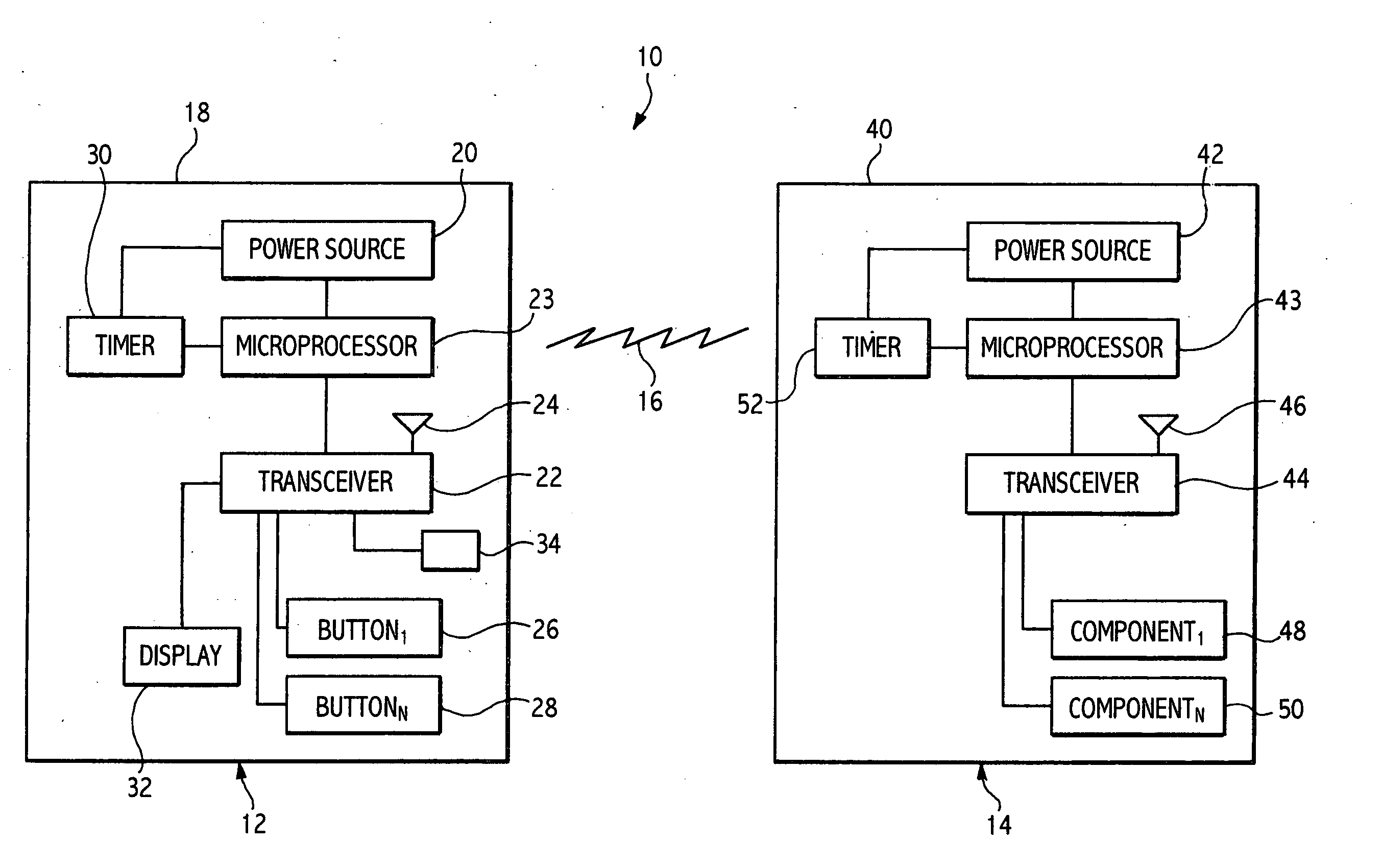
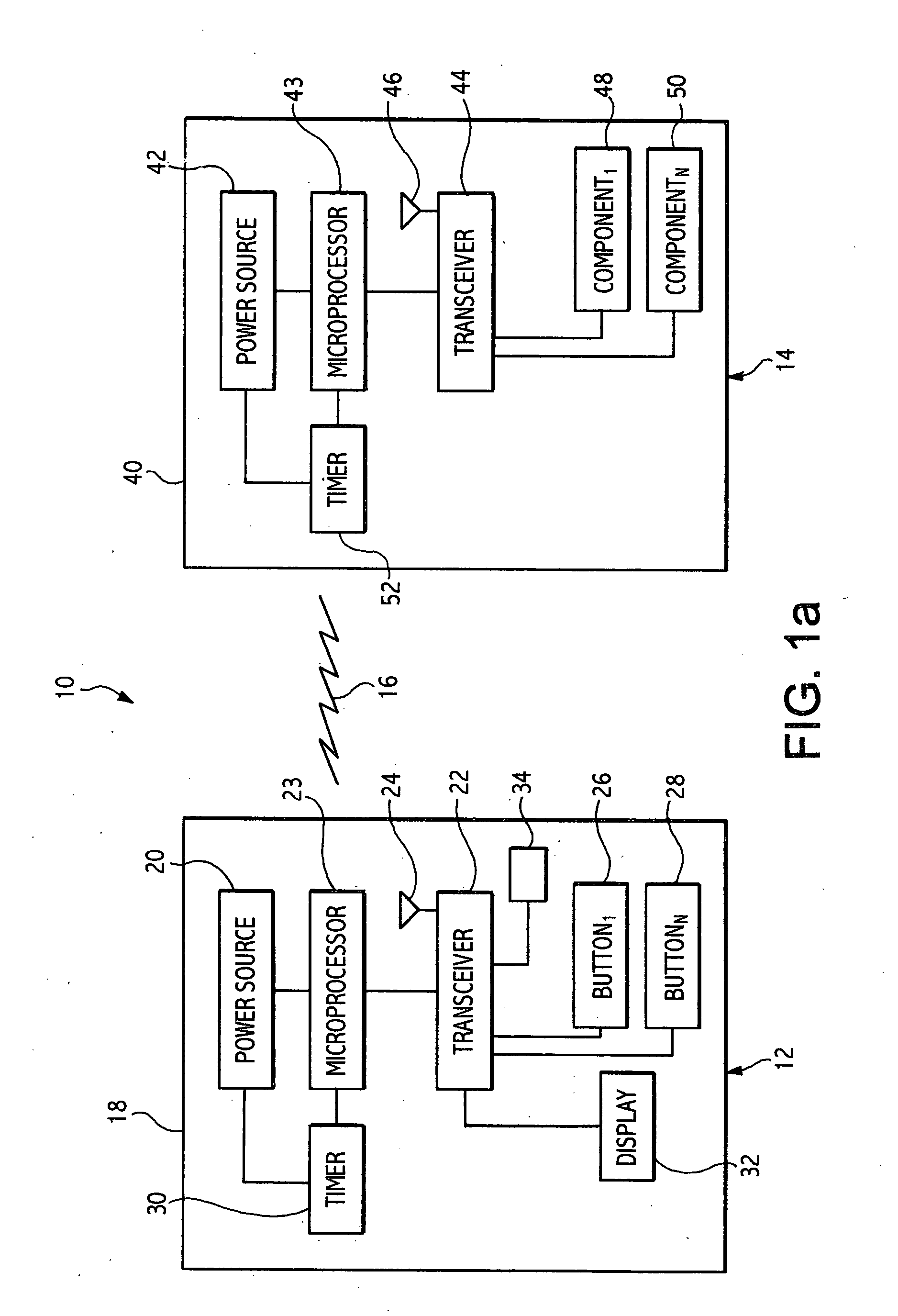
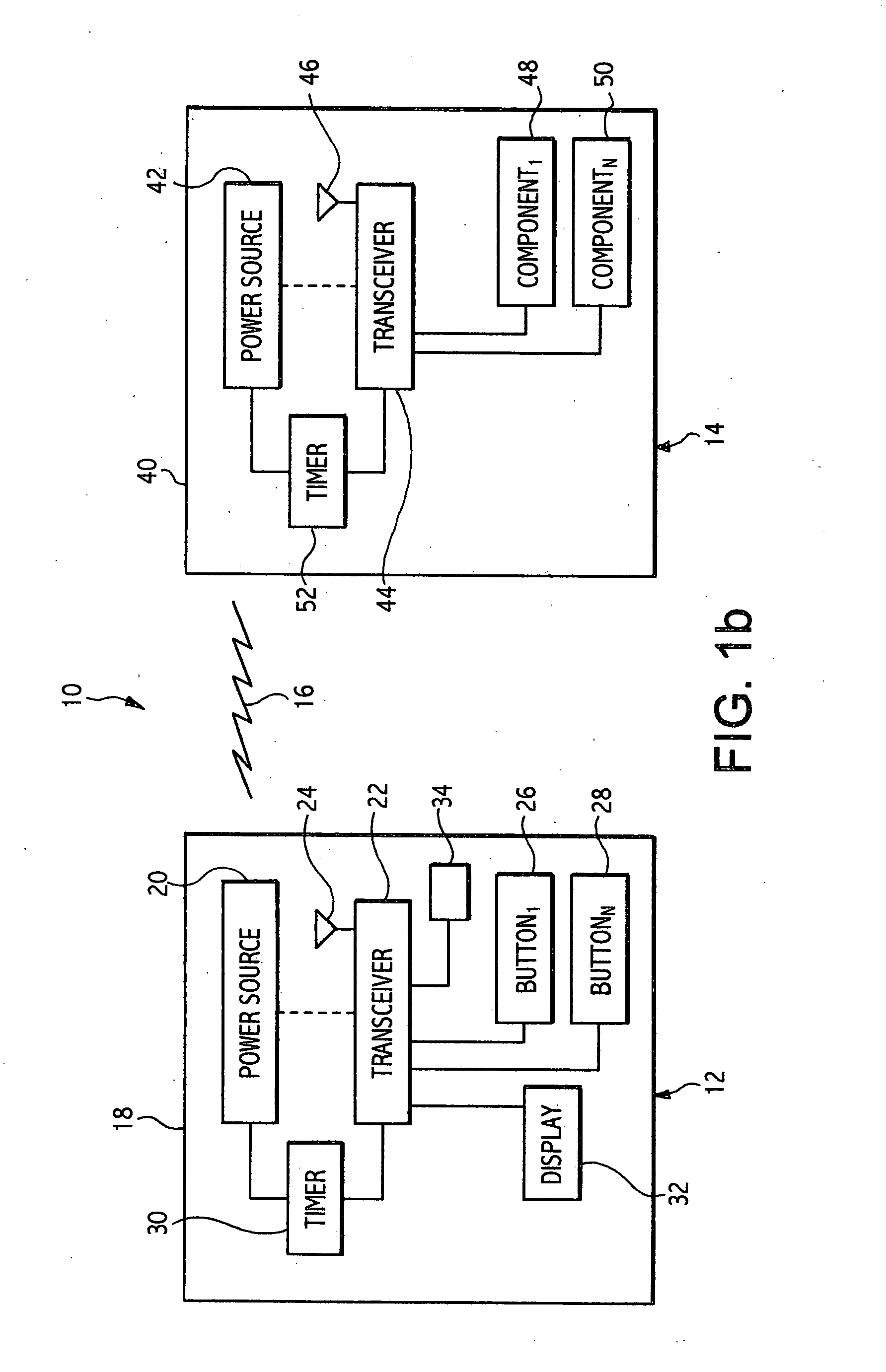
[0006] A two way remote communication system for a vehicle in accordance with the present invention includes a key fob having an electrical power source, such as a battery or the like, and a fob transceiver that is operable to transmit and receive electrical signals disposed in the key fob and electrically connected to the fob battery. At least one button is disposed in the key fob and is electrically connected to the fob transceiver. The button is operable to initiate a transmission of a command by the fob transceiver. A fob timer is electrically connected to the fob transceiver and the fob battery. The communication system also includes a vehicle having an electrical power source, such as a battery or the like. A vehicle transceiver operable to transmit and receive electrical signals is disposed in the vehicle and is electrically connected to the vehicle battery. At least one electrical component is electrically connected to the vehicle transceiver and is operable to receive signals from and transmit commands to the vehicle transceiver. A vehicle timer is electrically connected to the vehicle transceiver and the vehicle battery. The fob and vehicle transceivers are operable to transmit and receive electrical signals in response to commands transmitted by the at least one button and the at least one electrical component. The fob and vehicle timers are synchronized to simultaneously activate and deactivate the transceivers to establish periodic time intervals when the transceivers are open to transmission, thereby establishing idle time for the transceivers and reducing the amount of power consumed by the fob battery.

Problems solved by technology

Many of these systems, while providing enhanced and desirable features, disadvantageously tend to draw too much power from the fob battery due to the increased power requirements of a transceiver, resulting in a decreased fob battery life and decreased customer satisfaction.

Method used


Image

  • Vehicle two way remote communication system
  • Vehicle two way remote communication system
  • Vehicle two way remote communication system

Examples


Embodiment Construction

[0013] Referring now to FIGS. 1a and 1b, a two way remote communication system in accordance with the present invention is indicated generally at 10. The communication system 10 includes a remote portion, indicated generally at 12 and a vehicle portion, indicated generally at 14. The remote portion 12 and the vehicle portion 14 are operable to communicate with each other, discussed in more detail below via radio frequency waves, indicated generally at 16.

[0014] The remote portion 12 of the communication system 10 includes a fob, indicated schematically at 18, having a power source 20, such as a battery or the like, disposed therein. The fob 18 is preferably sized to be held by a human hand and is preferably adapted to be attached to a vehicle key chain (not shown) or the like. A microprocessor 23 is disposed in the fob 18 and is electrically connected to the battery 20. The microprocessor 23 is operable to activate and deactivate a transceiver 22. The transceiver 22 is disposed in ...


PUM


Abstract

A two way remote communication system for a vehicle includes a fob portion and a vehicle portion. The fob portion includes a fob battery, a fob transceiver, at least one button and at least one display. The vehicle portion includes a vehicle battery, a vehicle transceiver, and at least one electrical component. The timers are synchronized to simultaneously activate and deactivate the transceivers to establish periodic time intervals when the fob transceiver is open to transmission, which establishes idle time for the fob transceiver and reduces the amount of power consumed by the fob battery.

Description

CROSS REFERENCE TO RELATED APPLICATIONS [0001] Not Applicable. STATEMENT REGARDING FEDERALLY SPONSORED RESEARCH [0002] Not Applicable. BACKGROUND OF THE INVENTION [0003] The present invention relates generally to remote keyless entry systems for vehicles and, in particular, to a two way remote communication system for a vehicle. [0004] Remote keyless entry systems are well known and typically include a key fob having a transmitter carried by a person that communicates with a receiver assembly in the vehicle. Recent improvements to remote keyless entry systems include two-way communication functionality utilizing respective transmitter / receiver assemblies (i.e., transceivers) in the vehicle and the key fob. Many of these systems, while providing enhanced and desirable features, disadvantageously tend to draw too much power from the fob battery due to the increased power requirements of a transceiver, resulting in a decreased fob battery life and decreased customer satisfaction. [0005...

Claims


Application Information

Patent Timeline
IPC IPC(8): B60R25/04B60R25/10G07C9/00G08C17/02G08C19/00H04L12/10
CPCB60R25/246B60R25/406G07C2209/62G07C2009/00793G07C2209/06G07C9/00309B60R25/04G08C17/02
Inventor GHABRA, RIADTANG, QINGFENGNANTZ, JOHN S.LUO, YI
Owner LEAR CORP
Learn More