
System and method for remotely controlling devices

a technology of remote control and device, applied in the field of system and method for remote control devices, can solve the problems of increasing the risk of inadvertent activation of one foot pedal, increasing the risk of asepsis or contamination problem, and achieving the effect of less clutter

Inactive Publication Date: 2005-06-16
CLUTTERFREE DENTAL SOLUTIONS
View PDF38 Cites 84 Cited by
  • Summary
  • Abstract
  • Description
  • Claims
  • Application Information

AI Technical Summary

Benefits of technology

[0008] The system and method for remotely controlling devices provides a substantial advantage over other systems and methods. In particular, the system and method provide a foot pedal unit having one movable member that can be utilized to control multiple devices. Thus, an operator of the foot pedal unit can obtain a consistent control of multiple devices. Further, the single foot pedal unit can replace a plurality of other foot pedal providing for a less cluttered operatory floor.

Problems solved by technology

Further, because the foot pedals are not standardized, each foot pedal often has a different level of control or “feel” such that the operator of the pedals fails to achieve a consistent level of control among the devices.
Further, multiple foot pedals may cause confusion and increase the risk of an inadvertent activation of one of the foot pedals.
Further, when a device associated with a foot pedal needs to be moved within an operatory room or between operatory rooms, an asepsis or contamination problem may occur.
In particular, the operatory room floor and the foot pedal or cable associated with the foot pedal may not be sufficiently clean such that when the device is moved with the associated pedal, the pedal may undesirably contaminate the device.

Method used


Image

  • System and method for remotely controlling devices
  • System and method for remotely controlling devices
  • System and method for remotely controlling devices

Examples


Embodiment Construction

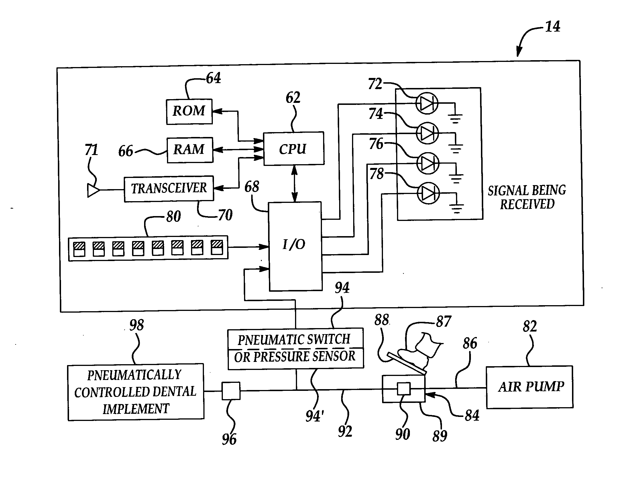
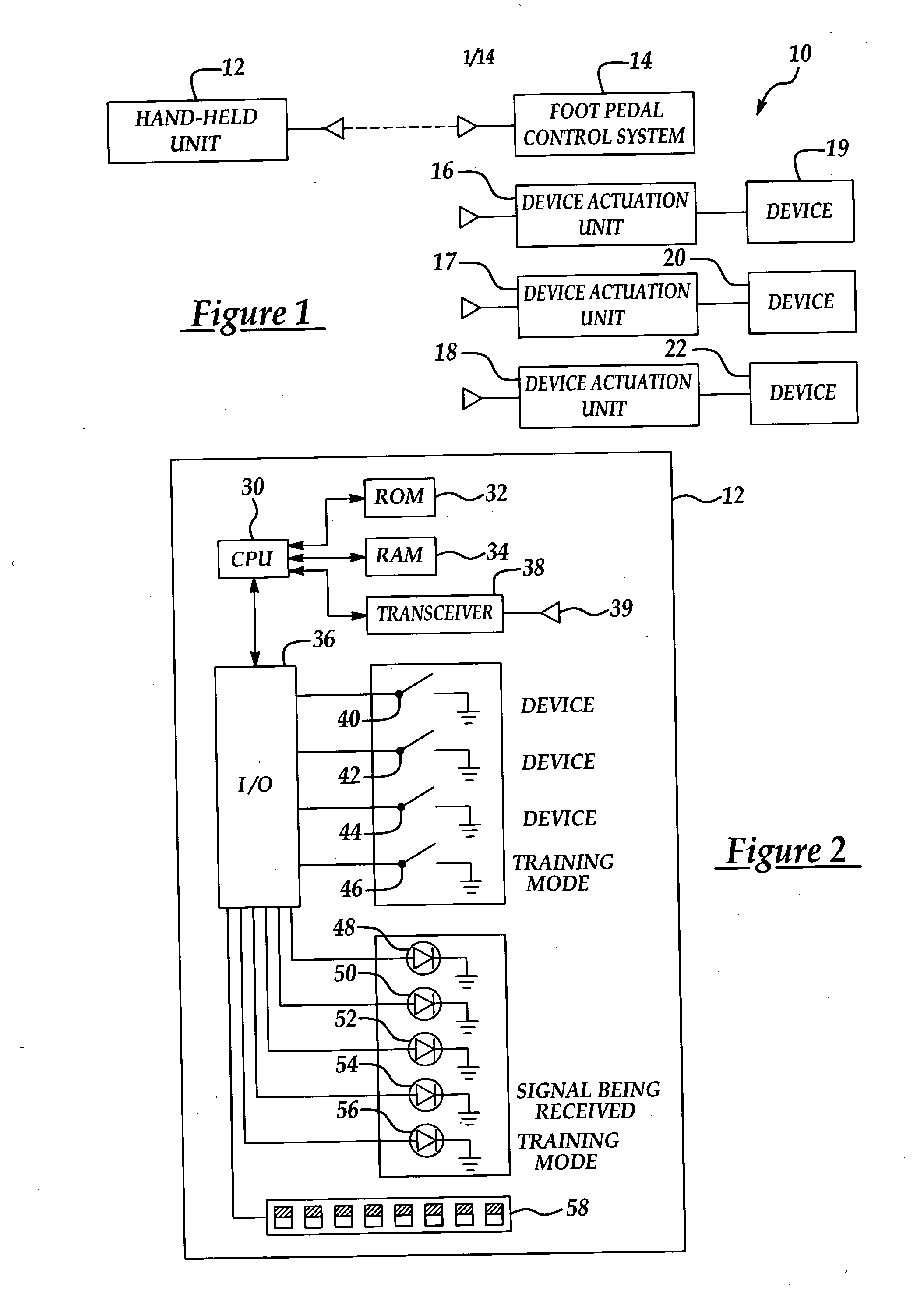
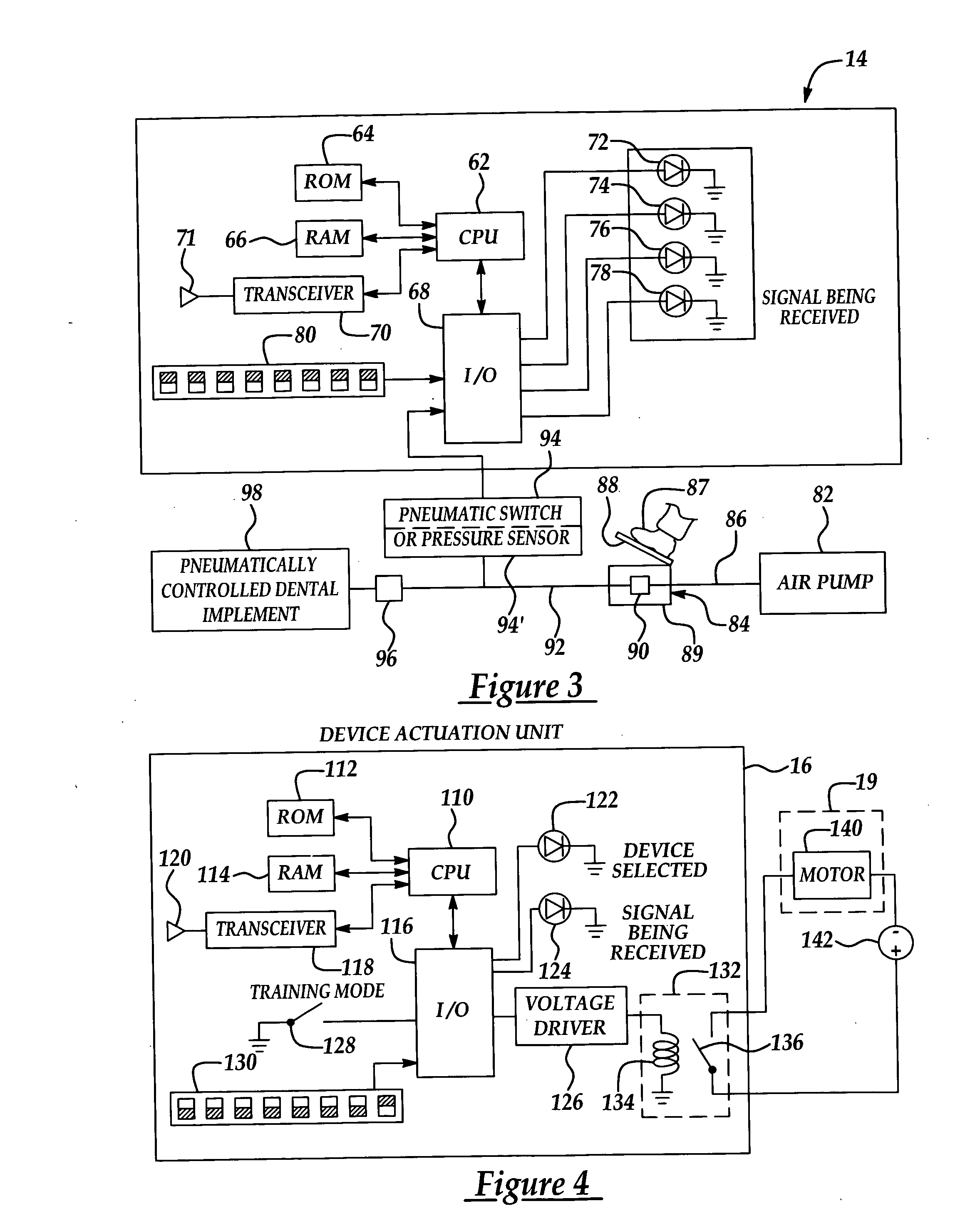
[0029] Referring now to the Figures, like reference numerals are used to identify identical components in the various views. Referring to FIG. 1, a system 10 for remotely controlling devices is illustrated. System 10 may include a handheld unit 12, a foot pedal control system 14, and a device actuation unit 16. System 10 may further include a device actuation unit 17, a device actuation unit 18, and devices 19, 20, 22. Device actuation units 17, 18 may have a substantially similar hardware configuration as device actuation unit 16. Although, system 10 will be described as utilizing RF signals to communicate with the various system components, it should be noted that in alternate embodiments of system 10, infrared signals, near-infrared signals, or magnetic signals could be utilized for communicating with one or more of the various system components. It should be further noted that although only three device actuation units are illustrated in FIG. 1, a plurality of additional device ...


PUM


Abstract

A system and a method for remotely controlling devices are provided. The system includes a foot pedal unit having a moveable member. The system further includes a transmitter operatively associated with the moveable member. The transmitter transmits a first signal in response to at least partial displacement of the moveable member when a first device is selected. The transmitter transmits a second signal in response to at least partial displacement of the moveable member when a second device is selected.

Description

[0001] This application is a divisional application of U.S. patent application Ser. No. 10,730,678, filed Dec. 8, 2003. U.S. patent application Ser. No. 10,730,678 is a continuation-in-part of U.S. application Ser. No. 10 / 464,369, filed on Jun. 17, 2003 that claims priority to U.S. Provisional Ser. No. 60 / 389,229, filed on Jun. 17, 2002.FIELD OF THE INVENTION [0002] This invention relates to a system and method for the remotely controlling devices. BACKGROUND OF THE INVENTION [0003] Dental professionals generally utilize a plurality of dental devices when performing dental procedures on patients. Each device or implement is generally controlled using a foot pedal. Thus, a dental operatory room generally has a plurality of foot pedals located on the floor to allow the dentist to control the plurality of devices. The inventor herein has recognized that multiple foot pedals and their associated conduits and cords are a hindrance to the operator's mobility due to multitude of different ...

Claims


Application Information

Patent Timeline
Patent Type & Authority Applications(United States)
IPC IPC(8): A61B17/00A61C1/00A61C1/02
CPCA61B2017/00973A61C1/0023A61C1/0015
Inventor WARNER, THOMAS P.
Owner CLUTTERFREE DENTAL SOLUTIONS
Learn More