Power source apparatus supplying multiple output

a power source and output technology, applied in the direction of electric variable regulation, process and machine control, instruments, etc., can solve the problems of increasing the cost of the entire device, power source is not suitable for applications for which none of those settings are appropriate, and the efficiency cannot be optimized, so as to achieve the effect of optimizing efficiency

Inactive Publication Date: 2005-06-16
TAIYO YUDEN KK
View PDF8 Cites 13 Cited by
  • Summary
  • Abstract
  • Description
  • Claims
  • Application Information

AI Technical Summary

Benefits of technology

[0019] With the present invention, because a multiple output power source apparatus is constructed by employing a combination of at least two power source circuits having independent control circuits, the efficiency can be optimized for each output voltage and simultaneous shutdown and synchronous oscillations are possible between any output voltages.

Problems solved by technology

As a result, the efficiency cannot be optimized.
As a result, the power source is not suitable for applications for which none of those settings is appropriate.
In order to make the power source suitable for such applications, the circuits and components for this purpose have to be added, thereby raising the cost of the entire device.
As a result, optimum phase setting corresponding to each output voltage cannot be made.
As a result, the effect of external noise on the wiring causes unstable operation and malfunction.
Moreover, the noise produced by the wiring affects the external circuits.
Because power source circuits corresponding to each output voltage operate independently from each other, this configuration cannot cope with the situation of shutting down all the output voltages together, and the circuits and components to cope with this situation have to be added to resolve this problem, thereby raising the cost of the entire device.
Because power source circuits corresponding to each output voltage operate independently from each other, synchronous oscillations cannot be conducted between specific output voltages.
As a result, beat noise is generated.
However, with the technique described in Japanese Patent Application Publication No. 08-256471, it was necessary to provide a complex relay circuit outside the DC-DC converter, which made it inappropriate from the standpoint of miniaturizing the device.

Method used


Image

  • Power source apparatus supplying multiple output
  • Power source apparatus supplying multiple output
  • Power source apparatus supplying multiple output

Examples


Embodiment Construction

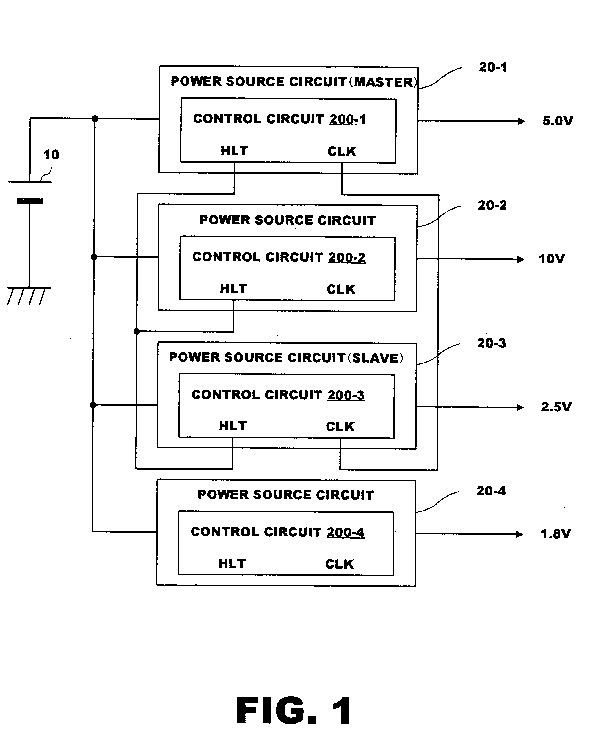
[0032] Embodiment of the multiple output power source apparatus in accordance with the present invention will be described hereinbelow with reference to the appended drawings. FIG. 1 is a block diagram illustrating an embodiment of the multiple output power source apparatus in accordance with the present invention.

[0033] The multiple output power source apparatus shown in FIG. 1 is composed, for example, by connecting a voltage-up-down power source circuit (master) 20-1, a voltage-up power source circuit 20-2, a voltage-down power source circuit (slave) 20-3, and a voltage-down power source circuit 20-4 in parallel to a power source 10 generating a voltage of 3.0 V to 5.5 V. In this device, a voltage of 5.0 V is outputted from the voltage-up-down power source circuit 20-1, a voltage of 10 V is outputted from the voltage-up power source circuit 20-2, a power source voltage of 2.5 V is outputted from the voltage-down power source circuit 20-3, and a voltage of 1.8 V is outputted from...


PUM


Abstract

Multiple output power source apparatus enables to optimize efficiency for each output and to perform simultaneous shutdown and synchronous oscillations between the outputs. Power source circuits of various types connected to a power source are provided, and those power source circuits have a function of outputting an abnormality signal to other power source circuits when an abnormality occurs in the own circuit and shutting down the operation of the own circuit by an abnormality signal from other power source circuits and a function of outputting a synchronous oscillation signal synchronized with a switching oscillation frequency used for controlling the own circuit to other power source circuits and conducting synchronous control of the switching frequency used for controlling other power source circuits.

Description

BACKGROUND OF THE INVENTION [0001] 1. Field of the Invention [0002] The present invention relates to a multiple output power source circuit for outputting a plurality of voltages, and more particularly to a multiple output power source circuit in which at least two of a plurality of power source circuits are provided with independent control circuits, thereby increasing decentralization and efficiency of the multiple output power source. [0003] 2. Description of the Related Art [0004] The conventional multiple output power source circuits for outputting a plurality of voltages are known to have configurations in which [0005] a plurality of outputs are centralized-controlled with one control circuit (centralized control type); or [0006] a plurality of power control circuits of various types operating independently from each output are provided (decentralized control type). [0007] However, the following drawbacks are associated with the aforementioned configuration 1) of the centraliz...

Claims


Application Information

Patent Timeline
Patent Type & Authority Applications(United States)
IPC IPC(8): H02J1/08H02M3/00H02M3/10
CPCH02J1/08H02J2001/008H02M2001/008H02M3/10H02M1/32H02J1/082H02M1/008
Inventor OKADA, TERUONAKAJIMA, RYUYAOOYA, MITSUAKIISHIDA, SHINICHI
Owner TAIYO YUDEN KK
Why Eureka
Try Eureka