
Sealing structure for convertible type vehicle

Active Publication Date: 2005-06-16
NISHIKAWA RUBBER
View PDF4 Cites 9 Cited by
  • Summary
  • Abstract
  • Description
  • Claims
  • Application Information

AI Technical Summary

Benefits of technology

[0009] According to the invention, the fin shape seal portion seals a gap formed between the roofs like the sub-seal portion. The fin shape seal portion is smaller in rigidity compared to a hollow seal portion and is curved, so that it is easily bent when it impinges to the hollow seal portion of the weather strip when the roof is in a closed position. Further, since the contact area of the fin shape seal portion against the hollow seal portion of the weather strip is larger, the stress applied to the hollow seal portion is dispersed. Those facts enable to make the hollow seal portion of the weather strip hardly deform, thereby making the hollow seal portion not to impair its sealing performance against the hood of the vehicle.

Problems solved by technology

However, the former method using the EPT sealer induces an increase of a production cost, whereas the latter method forming the hole or holes in the roof side weather strip 22 has a difficulty in draining the water invading from the direction shown with the arrow in FIGS. 11 and 12 when a quantity of the invading water is large at a time of a car wash with highly pressured water.

Method used


Image

  • Sealing structure for convertible type vehicle
  • Sealing structure for convertible type vehicle
  • Sealing structure for convertible type vehicle

Examples


Embodiment Construction

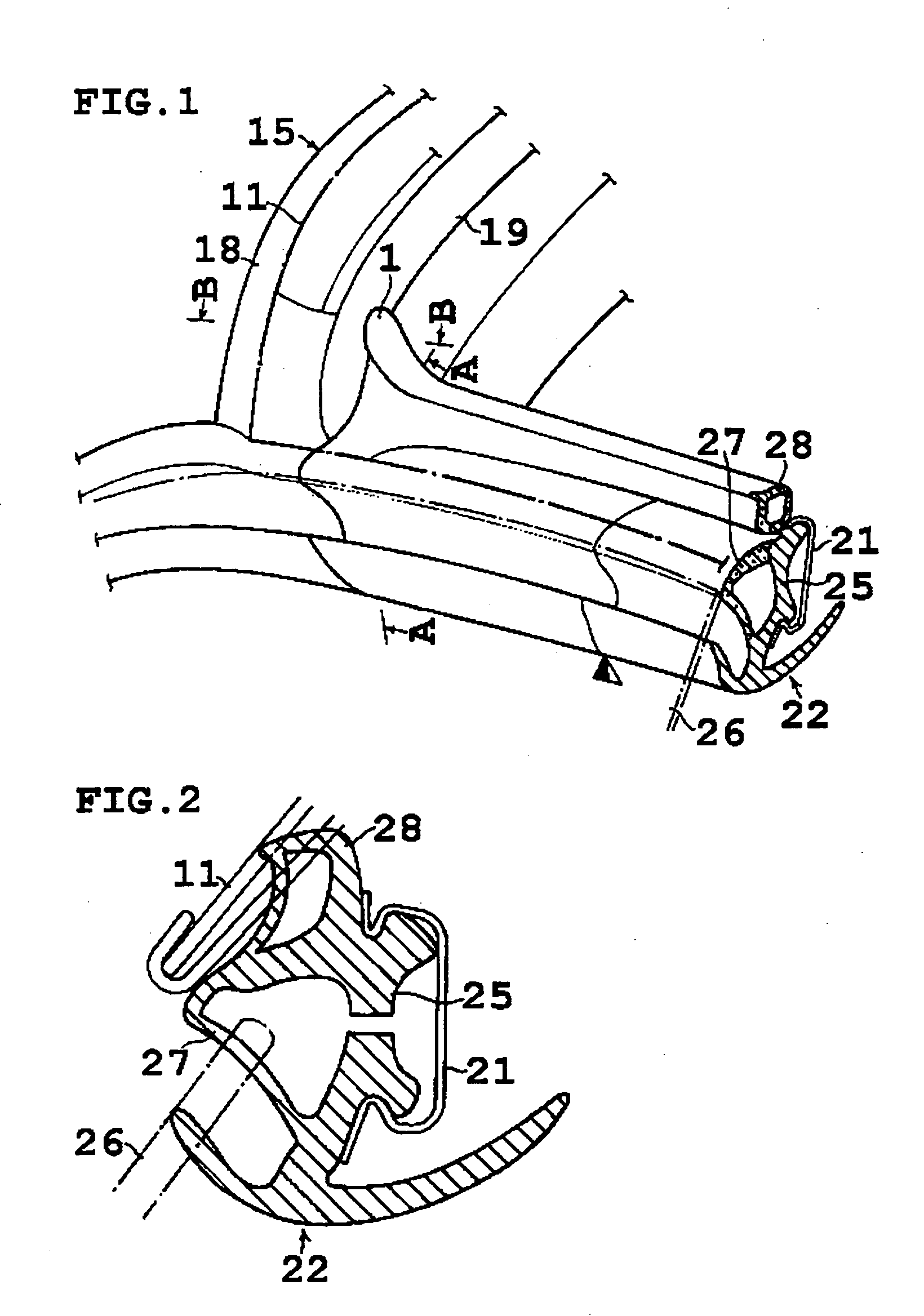
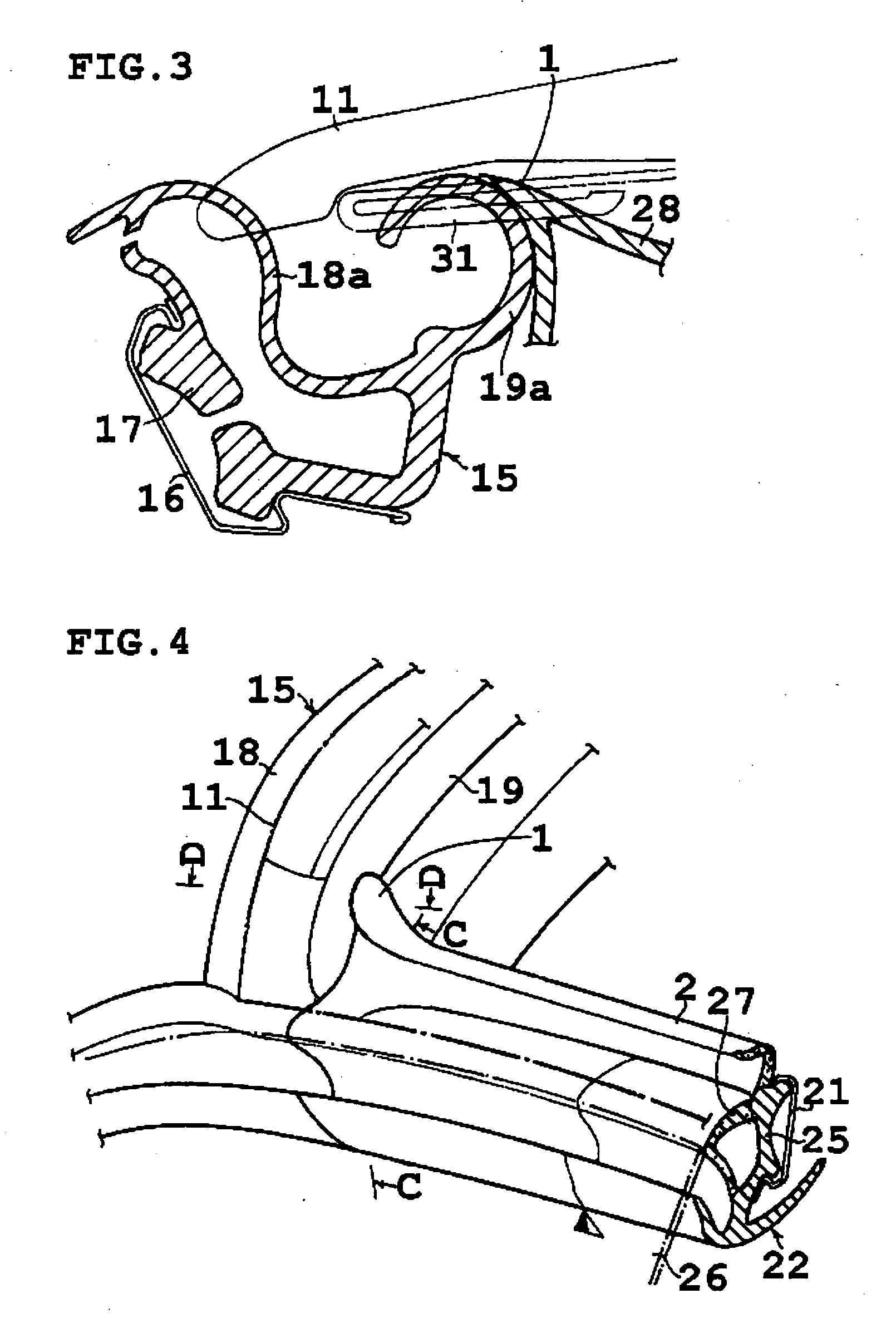
[0023] A sealing structure according to a preferred embodiment of the invention will be described hereinafter referring to FIGS. 1 to 8. In the drawings, same numerals are applied to portions which correspond to similar portions in the conventional sealing structure illustrated in FIGS. 9 to 12.

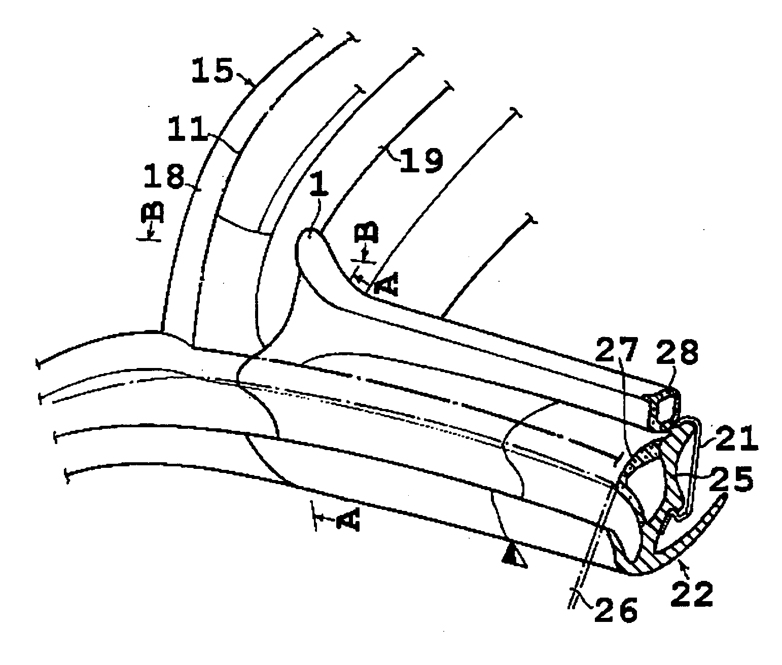
[0024] FIGS. 1 to 3 illustrate a sealing structure according to a first preferred embodiment of the invention wherein FIG. 1 shows a structure in which, when a hood 11 forming a roof is in a closed position, a die molded front end of a roof side weather strip 22 mounted along a side edge of a hood 11 is making a contact with a die molded corner portion of a weather strip 15 which is mounted along a header 12 which extends sideward from a top of end of the front pillar 13 and secures a top end of a front glass 14, and a front pillar 13. FIG. 2 is a sectional view along A-A line in FIG. 1, and FIG. 3 is a sectional view along line B-B in FIG. 1.

[0025] Hollow sealing portions 18a and 19a conne...


PUM


Abstract

There is provided a sealing structure in a convertible type vehicle in which a roof 11 is opened by folding or removing the roof 11, wherein a weather strip 15 mounted to a header 12 comprises seal portions 18, 19, which seals a gap by making a resilient contact with the hood 11 when the hood 11 is in a closed position. A roof side weather strip 22 mounted to a side edge of the hood 11 comprises a sub-seal portion 28 which seals a gap formed with the hood 11. A fin shape seal portion 1 is projecting formed at a front end of the sub-seal portion 28, where a front end of the seal portion 1 makes a resilient contact with a seal portion 19 of the weather strip 15 when the hood 11 is in a closed position, thereby sealing a contacting portion formed between the weather strip 15 and the front end of the roof side weather strip 22.

Description

BACKGROUND OF THE INVENTION [0001] This invention relates to a sealing structure formed at a portion where a weather strip mounted along a header and a front pillar of a vehicle makes a contact with a front end of a roof side weather strip in a convertible type vehicle comprising a roof which opens by being folded or removed. [0002]FIG. 9 illustrates a convertible type vehicle comprising a foldable hood 11 which forms a roof, wherein the hood 11 is stored at a backside of a vehicle body when it is folded to open the roof, while a front end of the hood 11 makes a contact with a header 12 and a top end of a front pillar 13 when it is in a closed position. [0003]FIG. 10 illustrates a view of a portion positioned along a header 12 in a weather strip 15 which is mounted to a header which extends sideward from a top end of a front pillar 13 and a front pillar 13. The header 12 secures a top end of a front glass 14. The weather strip 15 comprises a mounting base portion 17 being mounted to...

Claims


Application Information

Patent Timeline
IPC IPC(8): B60R13/06B60J10/90
CPCB60J10/10B60J10/90
Inventor TSUCHIDA, HIDESHI
Owner NISHIKAWA RUBBER
Learn More