
Bracket system for attaching elongated members

Inactive Publication Date: 2005-06-16
CERTAINTEED CORP
View PDF23 Cites 33 Cited by
  • Summary
  • Abstract
  • Description
  • Claims
  • Application Information

AI Technical Summary

Benefits of technology

[0020] It is an object of the invention to provide a rail-and-post connection that is versatile for accommodating different construction situations such as different relative angles of the rail and post, structurally strong, easy to assemble and attractive in the finished state. Another object is to do so in elements that are inexpensive but durable and substantially maintenance free.
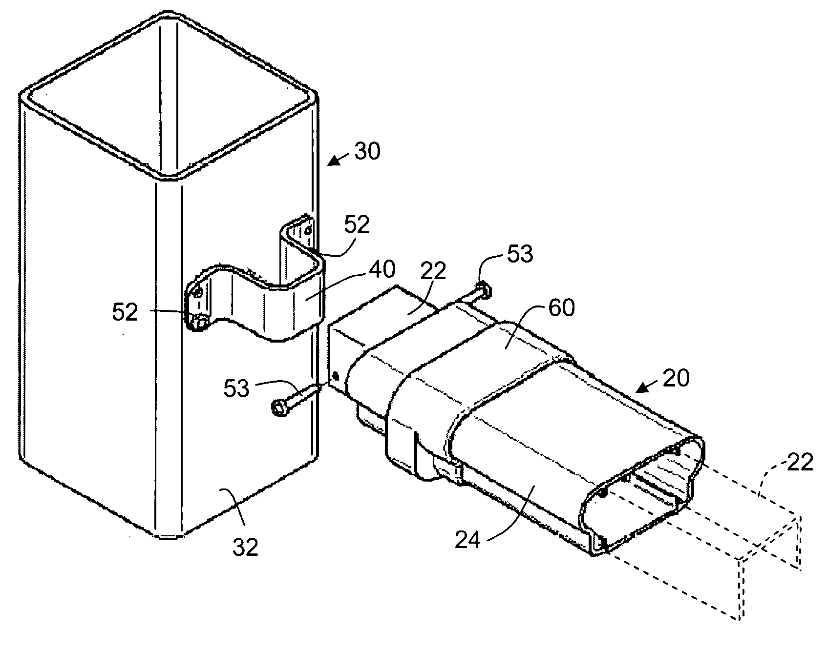
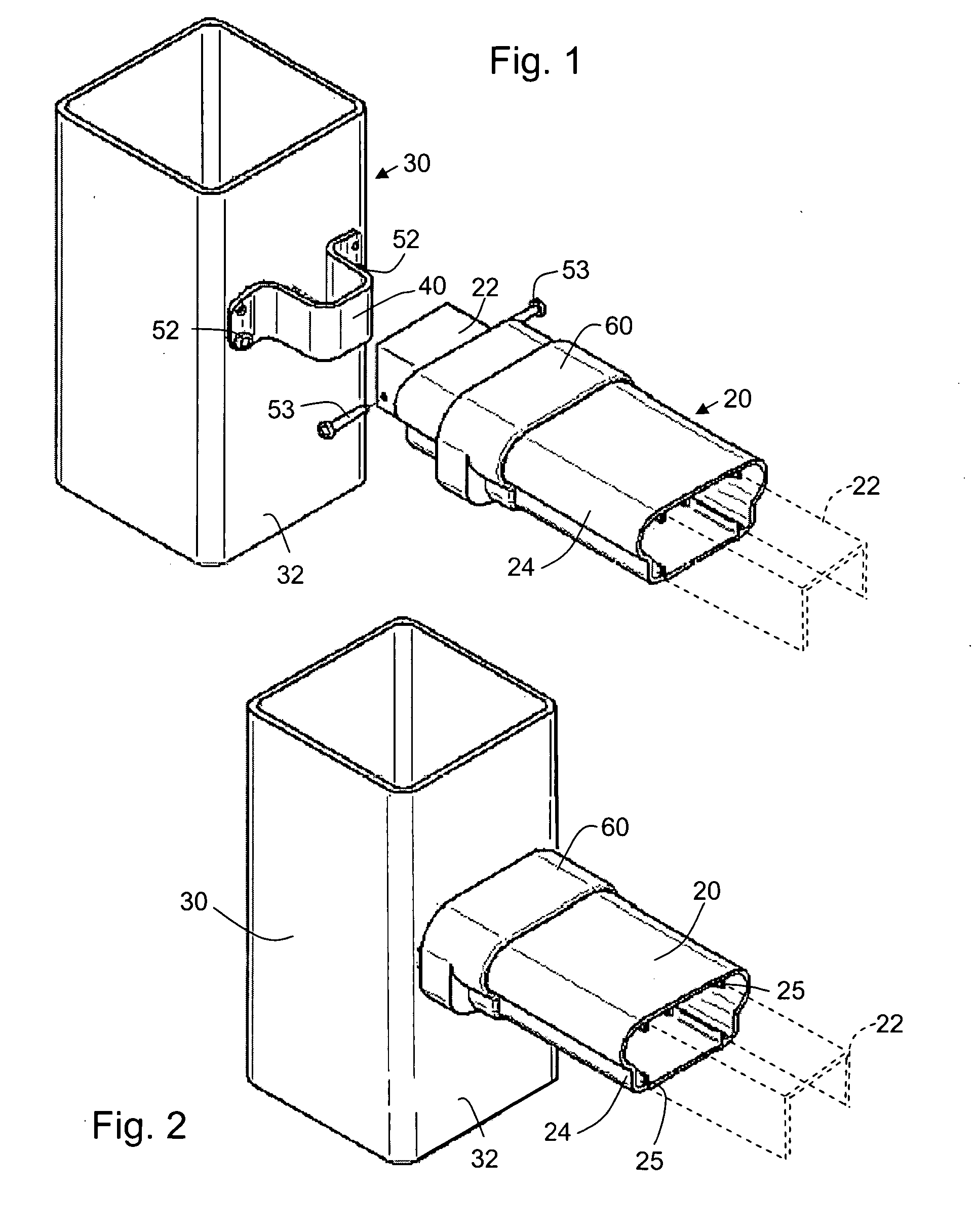
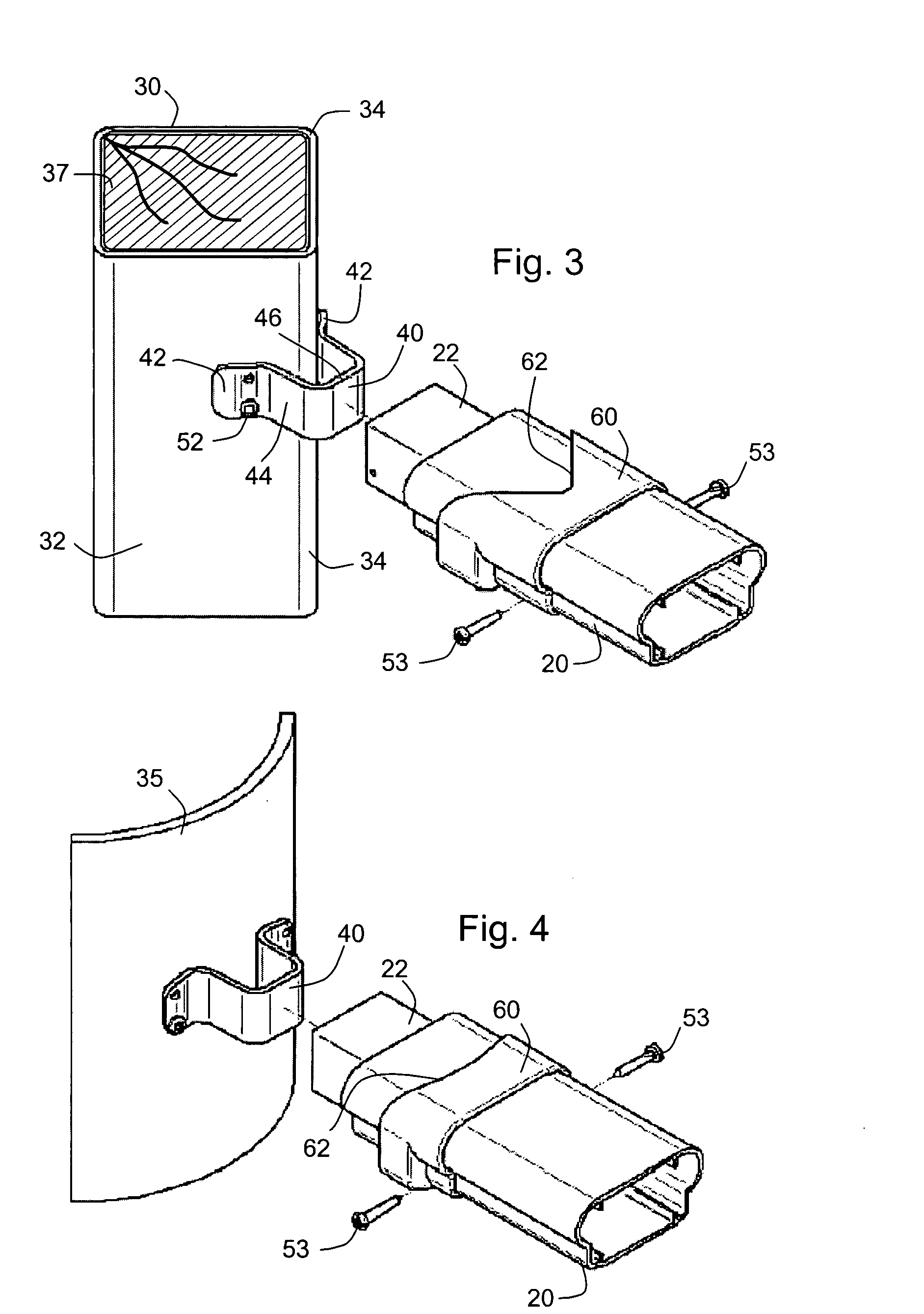
[0021] According to an aspect of the invention, elongated members such as the rail and post of a baluster are attached by a U-shaped bracket strip affixed on a surface of the post and received in an end of the rail, being attached to each by fasteners. A terminal fitting forms a sleeve that is provided or is shaped during installation to conform to the surface of the post. The terminal fitting sleeve extends over the end of the rail and over the bracket, to abut against the post, concealing the end of the rail. The rail can have a flush cut load bearing internal member such as an aluminum channel or rectangular tube. A polymer outer cover forms the surface of the rail. Either or both of the internal member and the polymer outer cover can be slant cut or coped, but the invention minimizes or eliminates the need for complex coping cuts. The bracket system makes convenient, useful and structurally strong rail-to-post connections at various angles and in situations where the rail needs to meet the post at a polygonal edge.
[0022] According to an inventive aspect, the U-shaped bracket strip fits snugly into the opening in the load bearing internal member, and the opposite ends of the bracket strip are folded to provide feet at angles that determine the relative orientation of the body of the U-shaped bracket relative to the post. This also determines the nominal angle of the rail. The bracket strips are inexpensive, and can be provided pre-formed to a number of angles from which the installer selects the appropriate angle. It may also be possible to shape the bracket on site, but this can be complicated in the same way as complex coping cuts, and therefore is not preferred.

Problems solved by technology

It may also be possible to shape the bracket on site, but this can be complicated in the same way as complex coping cuts, and therefore is not preferred.

Method used


Image

  • Bracket system for attaching elongated members
  • Bracket system for attaching elongated members
  • Bracket system for attaching elongated members

Examples


Embodiment Construction

[0033] A number of exemplary embodiments of the invention are described herein with reference to the drawings. These embodiments are examples intended to demonstrate aspects of the invention in different forms or separately. Not all the aspects are required in all embodiments of the invention, and the illustrated embodiments should be regarded as exemplary rather than limiting.

[0034] Furthermore, this description is written to refer to examples that do not exclude comparable structures and functions. For example, the vertical member of a post and rail construction is often the thicker and more securely mounted of the two members that are joined, is most often vertical, and is generally called the “post.” The rail is likely to be more lightweight and less securely affixed to other structures. The rail is usually abutted endwise against the lateral side of a post at the joint. Although often horizontal, rails sometimes reflect the ground contour or the inclined slope of a stairway. N...


PUM


Abstract

Elongated members such as the rail and post of a baluster are attached by a U-shaped bracket strip affixed on a surface of the post and received in an end of the rail, being attached to each by fasteners. A terminal fitting forms a sleeve that is provided or is shaped during installation to conform to the surface of the post. The terminal fitting sleeve extends over the end of the rail and over the bracket, to abut against the post, concealing the end of the rail. The rail can have a flush cut load bearing internal member such as an aluminum channel or rectangular tube. A polymer outer cover forms the surface of the rail. The bracket system makes convenient, useful and structurally strong rail-to-post connections at various angles and in situations where the rail needs to meet the post at a polygonal edge.

Description

BACKGROUND OF THE INVENTION [0001] The invention relates to attachments of elongated members at an angle, particularly joints between elongated rails and posts. The invention is applicable, for example, to stair, deck or balcony railings and to fences of various types, and also can join rails and rail-like elements to adjacent walls as well as line posts, end posts and corners, porch posts, newels and the like. PRIOR ART [0002] Joints between elongated members are made in various indoor and outdoor contexts in which the members may lend structural support or may provide decoration, or both. An example is a joint between a vertical standing member (a post) and an elongated member that connects to the vertical one (a rail). In buildings, posts generally support beams that are exclusively horizontal and carry further structures whose weight is transferred to the posts. In open work structures such as fences and railings, rails may support elements with a decorative and / or confining fun...

Claims


Application Information

Patent Timeline
IPC IPC(8): A47H1/104A47H1/144
CPCA47H1/144A47H1/104
Inventor STEFFES, STEPHEN W.
Owner CERTAINTEED CORP
Learn More