
Self propelled gurney and related structure confidential and proprietary document

a self-propelled gurney and related technology, applied in the field of gurneys, can solve the problems of gurneys becoming extremely heavy and cumbersome to control, gurneys still being large and very heavy when occupied, and still a risk of back or other personal injury on the part of operators, so as to increase or reduce increase the speed of travel, and mount quickly to any gurney. , the effect of reducing the risk of back or other personal

Active Publication Date: 2005-06-16
GEROPHARM
View PDF17 Cites 51 Cited by
  • Summary
  • Abstract
  • Description
  • Claims
  • Application Information

AI Technical Summary

Benefits of technology

[0007] Another object of the present invention is to provide modular units which will easily and quickly mount to any gurney without need of modifying said gurney.
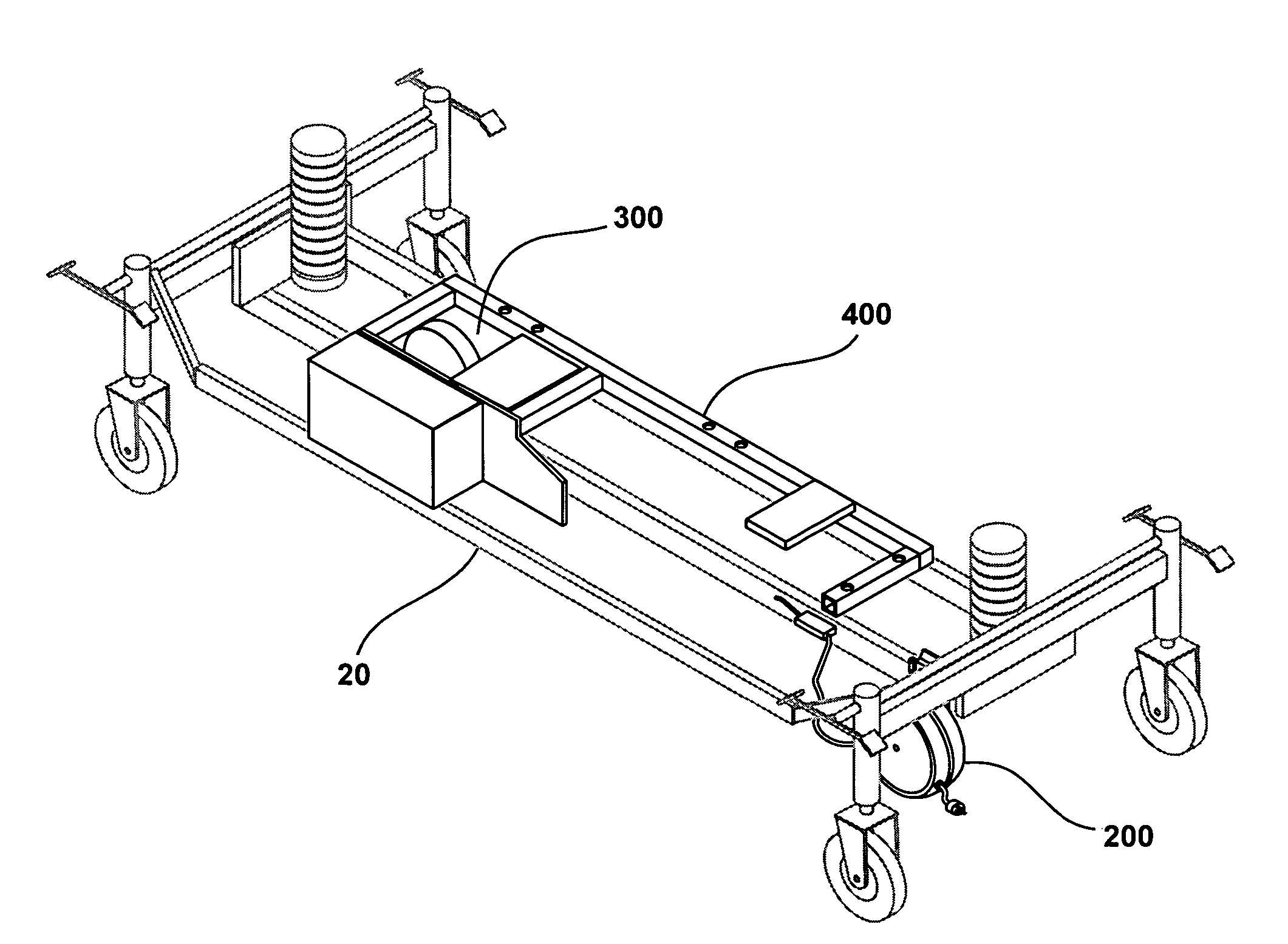
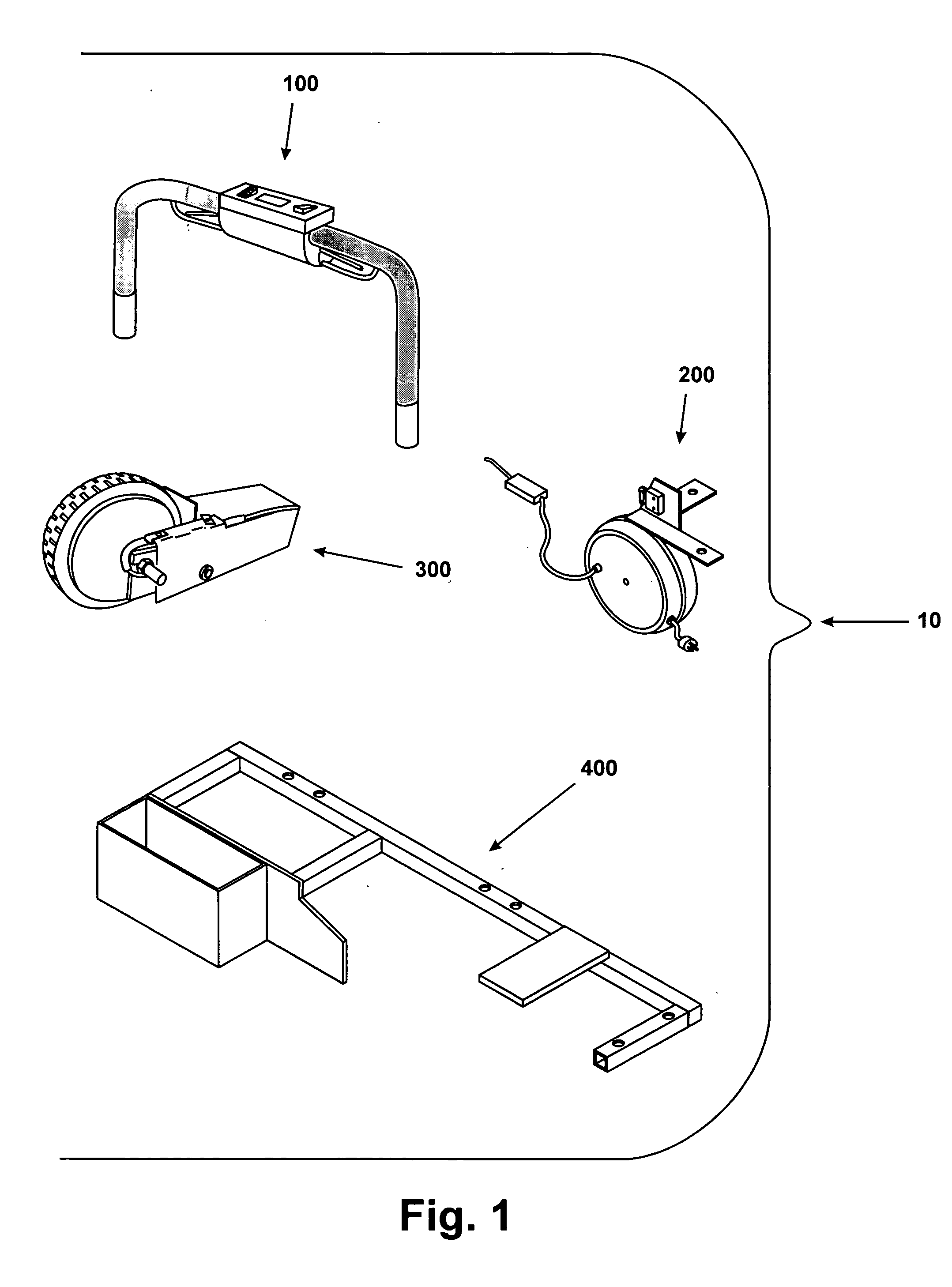
[0009] The present invention comprises a series of modules, including a control / handle module, a cord reel / charger module, a drive module, and a chassis assembly, plus all needed electrical wiring harnesses and pneumatic tubing to connect them. Also included are means to mount the modules to any existing gurney and to each other without making permanent modifications to the gurney. The gurney is controlled by a handle assembly containing all necessary controls and indicators to allow the operator to select forward or reverse direction, increase or reduce speed of travel, observe the state of battery charge, and energize or deenergize power from the various modules. In addition, the handle may be swung down through 180 degrees to facilitate loading and unloading the gurney.
[0012] When power is applied, the drive unit swivels down by means of a pneumatically actuated air spring that provides sufficient pressure on the floor to afford traction to the drive wheel. The drive unit also compensates for irregularities in the floor surface, such as a ramp, by increasing the air pressure in the air spring and forcing the drive unit farther down.

Problems solved by technology

When occupied by a patient, a gurney becomes extremely heavy and cumbersome to control, particularly on slanted or uneven surfaces.
However, the gurney is still large and very heavy when occupied, necessitating its operation by two or more people.
Even so, there is still a risk of back or other personal injury on the part of the operators.
Other motorized gurneys are in use, but they are purpose-built as powered units, which increases the cost.

Method used


Image

  • Self propelled gurney and related structure confidential and proprietary document
  • Self propelled gurney and related structure confidential and proprietary document
  • Self propelled gurney and related structure confidential and proprietary document

Examples


Embodiment Construction

[0025] In accordance with the present invention, FIG. 1 shows the present invention generally at 10, which comprises control / handle module 100, cord reel / charger module 200, drive module 300, and chassis assembly 400.

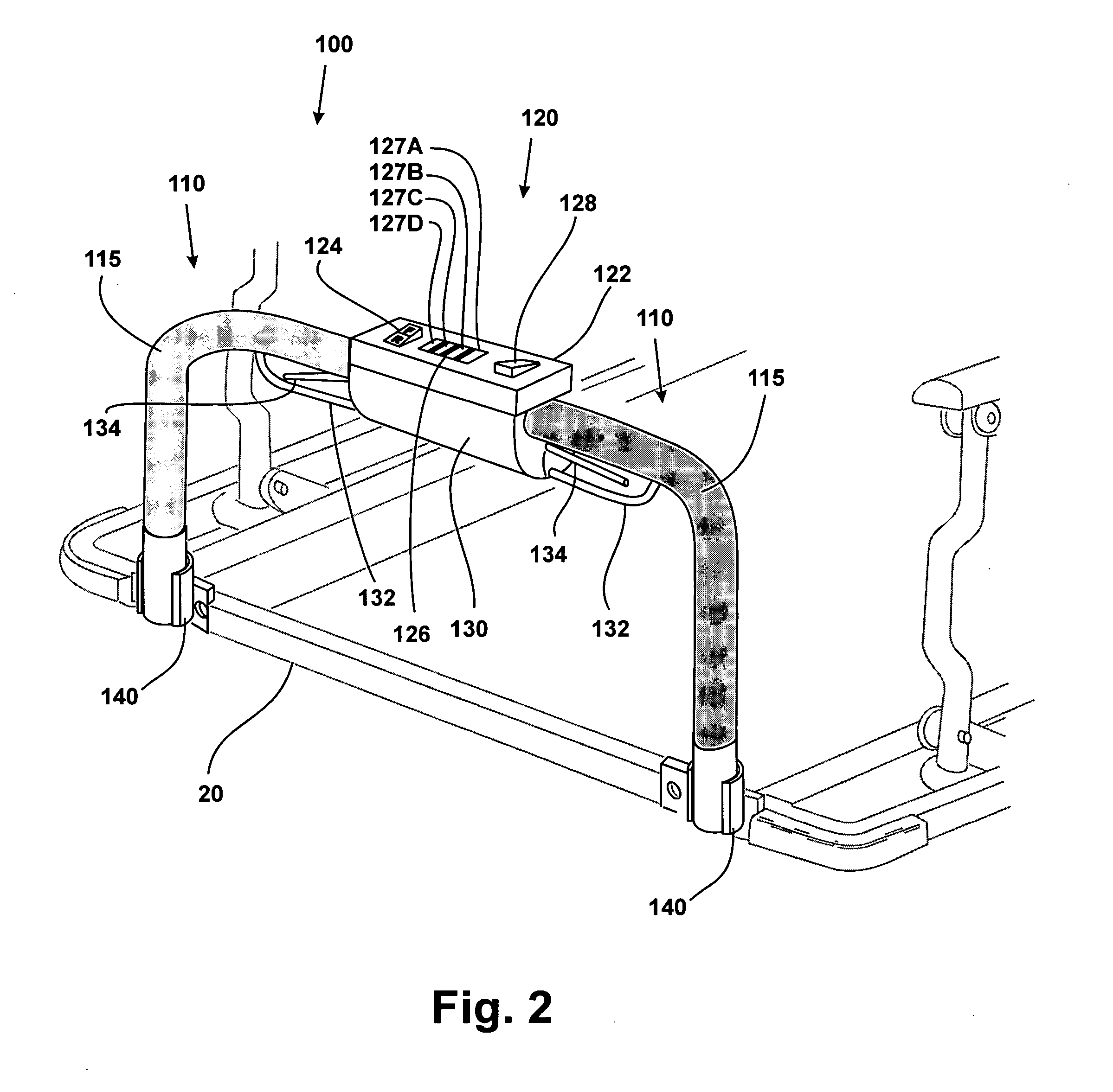
[0026]FIG. 2 shows control / handle module 100 in the normal position, mounted to a gurney 20 using mounting means 140. Handles 110 are made of steel, aluminum, carbon fiber, or other suitable material. Handles 110 are covered with a rubberized elastomeric substance 115, such as providing a non-slip grip for the operator.

[0027] Control assembly 120 is mounted to handles 110, is made of steel, aluminum, plastic or other suitable material, and comprises upper housing 122 and lower housing 130. Upper housing 122 contains directional switch 124, battery charge indicator 126, and on / off switch 128. Lower housing 130 contains throttle levers 134 and guards 132.

[0028]FIG. 3 shows handles 110 in their down position. This position is provided to easily load or unload a patient ...


PUM


Abstract

The present invention comprises a series of modules, including a control / handle module, a cord reel / charger module, a drive module, and a chassis assembly, plus all needed electrical wiring harnesses and pneumatic tubing to connect them. Also included are means to mount the modules to any existing gurney and to each other without making permanent modifications to the gurney. The gurney is controlled by a handle assembly containing all necessary controls and indicators to allow the operator to select forward or reverse direction, increase or reduce speed of travel, observe the state of battery charge, and energize or deenergize power from the various modules. In addition, the handle may be swung down through 180 degrees to facilitate loading and unloading the gurney.

Description

I FIELD OF THE INVENTION [0001] This invention relates to self-propelled hospital equipment, specifically gurneys. II BACKGROUND OF THE INVENTION [0002] Modular hospital gurneys are large, heavy pieces of equipment having a plurality of free castering wheels. When occupied by a patient, a gurney becomes extremely heavy and cumbersome to control, particularly on slanted or uneven surfaces. Directional control of gurneys has been improved in the past by the introduction of a small, unpowered, non-castering wheel in the center of the unit. This reduces the tendency of the gurney to move in random directions due to its castering wheels. However, the gurney is still large and very heavy when occupied, necessitating its operation by two or more people. Even so, there is still a risk of back or other personal injury on the part of the operators. [0003] Motorizing the gurney allows it to be easily handled by one person, and dramatically reduces the risk of personal injury on the part of the...

Claims


Application Information

Patent Timeline
IPC IPC(8): A61G1/02A61G7/05A61G7/08B60K1/00
CPCA61G7/08A61G2007/0528A61G1/0237A61G1/0281A61G1/0268A61G1/0275A61G1/0287A61G1/0225A61G7/0528
Inventor LENKMAN, THOMAS E.
Owner GEROPHARM
Learn More