
Loss of refrigerant charge and expansion valve malfunction detection

a technology of expansion valve and refrigerant charge, which is applied in the field of air conditioning and refrigeration systems, can solve the problems of insufficient factory charge, insufficient refrigerant charge amount, and likely damage to system components, such as compressors

Inactive Publication Date: 2005-06-16
CARRIER CORP
View PDF22 Cites 97 Cited by
  • Summary
  • Abstract
  • Description
  • Claims
  • Application Information

AI Technical Summary

Benefits of technology

This patent describes a method for monitoring the amount of refrigerant in a refrigerant system by measuring the superheat value of the refrigerant. This is done by determining the difference between the measured superheat value and an expected value, and comparing it to a selected threshold. This method can be used to detect a loss of refrigerant charge in the system, which can help to prevent damage or malfunctions. The patent also describes different ways to determine the superheat value, such as using the actual operating vapor temperature or the discharge temperature of the refrigerant. Overall, this invention provides a reliable and effective way to monitor the refrigerant system and ensure its proper functioning.

Problems solved by technology

If the refrigerant charge is reduced below a certain level, damage to the system components, such as the compressor, is likely.
Typical causes of inadequate refrigerant charge amounts include insufficient charge at the factory or during installation in the field or leakage through damaged components or loose connections.
While proposals have been made for detecting a loss of refrigerant charge, they are not universally applicable.
Further, known arrangements do not provide an early enough indication or are not reliable enough because they can be mistaken for some other system malfunctions such as an evaporator airflow blockage, compressor damage or a plugged distributor.
Using known techniques and trying to differentiate between such failure modes requires exhaustive troubleshooting.
Furthermore, other consequences of the refrigerant charge loss, such as detection of low suction pressure (i.e., by tripping on a low-pressure switch), usually occur late in the process and applying them may not prevent compressor damage.
Systems with these refrigerants are more prone to leaks.
Furthermore, expansion valves in refrigerant systems may malfunction (for example, due to contamination).
This in turn may lead to improper system operation and other component damage.

Method used


Image

  • Loss of refrigerant charge and expansion valve malfunction detection
  • Loss of refrigerant charge and expansion valve malfunction detection

Examples


Embodiment Construction

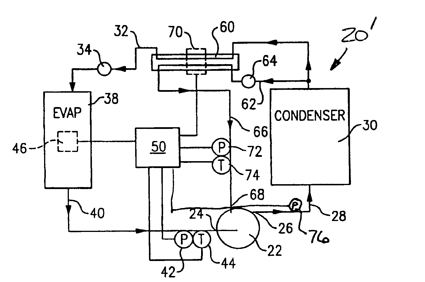
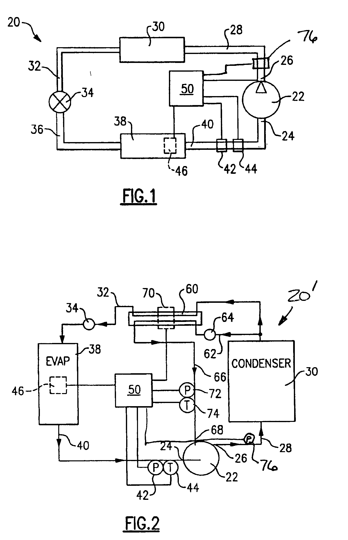
[0019]FIG. 1 schematically shows a refrigerant system 20 that may be used as an air conditioning or a refrigeration system. In a cooling mode, a compressor 22 draws refrigerant into a suction port 24 at low pressure and provides a compressed gas into a conduit 28 out of a discharge port 26. The high temperature, pressurized gas flows through the conduit 28 to a condenser 30 where the gas dissipates heat and usually condenses into a liquid as known. The liquid refrigerant flows through a conduit 32 to an expansion device 34.

[0020] The expansion device 34 operates in a known manner to allow the liquid refrigerant to expand and flow into a conduit 36 in the form of a cold, low pressure refrigerant. This refrigerant then flows through an evaporator 38 where the refrigerant absorbs heat from air that flows across the evaporator coil. Subsequently, cool air cools the desired space as known. The refrigerant exiting the evaporator 38 flows through a conduit 40 to the suction port 24 of the...


PUM

PropertyMeasurementUnit
operating vapor temperatureaaaaaaaaaa
saturated vapor temperatureaaaaaaaaaa
temperatureaaaaaaaaaa

Abstract

An actual superheat value in a refrigerant system is compared to an expected superheat level. If the actual superheat valve exceeds a certain predetermined value, this is an indication of refrigerant charge loss or a malfunctioning expansion device. In one example, the superheat valve is determined by comparing a difference between a saturated vapor temperature and an actual operating vapor temperature. The superheat determination can be made either at evaporator exit, economizer heat exchange exit or near the compressor discharge port.

Description

BACKGROUND OF THE INVENTION [0001] 1. Field of the Invention [0002] This invention generally relates to air conditioning and refrigeration systems. More particularly, this invention relates to detecting a loss of refrigerant charge within an air conditioning or refrigeration system. Furthermore, this invention can also be employed for identifying malfunctioning of the expansion valve. [0003] 2. Description of the Related Art [0004] Air conditioning and refrigeration systems need certain refrigerant charge within the system, to achieve a desired amount of cooling within a building, for example. If the refrigerant charge is reduced below a certain level, damage to the system components, such as the compressor, is likely. [0005] Typical causes of inadequate refrigerant charge amounts include insufficient charge at the factory or during installation in the field or leakage through damaged components or loose connections. [0006] It is necessary to detect a loss of refrigerant charge as e...

Claims


Application Information

Patent Timeline
Patent Type & Authority Applications(United States)
IPC IPC(8): F25B49/00
CPCF25B49/005F25B2400/13F25B2500/06F25B2700/2117F25B2500/222F25B2700/1931F25B2700/197F25B2500/19
Inventor LIFSON, ALEXANDERTARAS, MICHAEL F.DOBMEIER, THOMAS J.
Owner CARRIER CORP
Learn More