
Sensor for blood component analysis

a technology of blood component and sensor, which is applied in the field of blood component analysis, can solve the problems of affecting the normal eye health of diabetics whose eyesight is not very good, and the delicate operation of lancing and collecting blood has been a significant burden, and achieves the effect of less pain

Inactive Publication Date: 2005-06-09
PHC HLDG CORP
View PDF4 Cites 133 Cited by
  • Summary
  • Abstract
  • Description
  • Claims
  • Application Information

AI Technical Summary

Benefits of technology

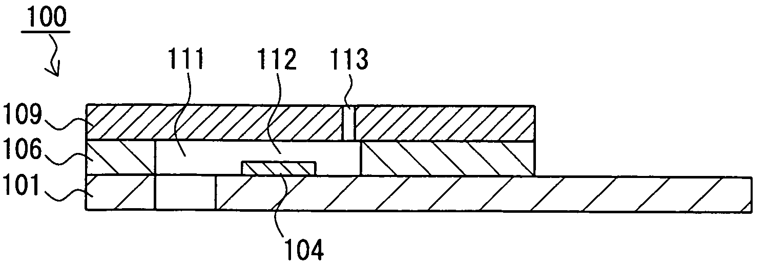
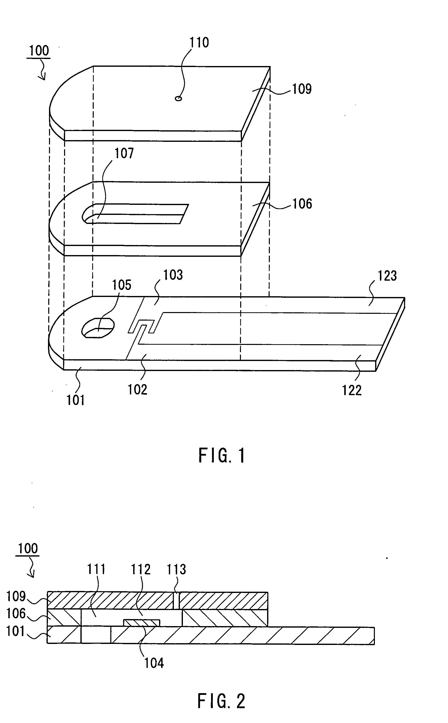
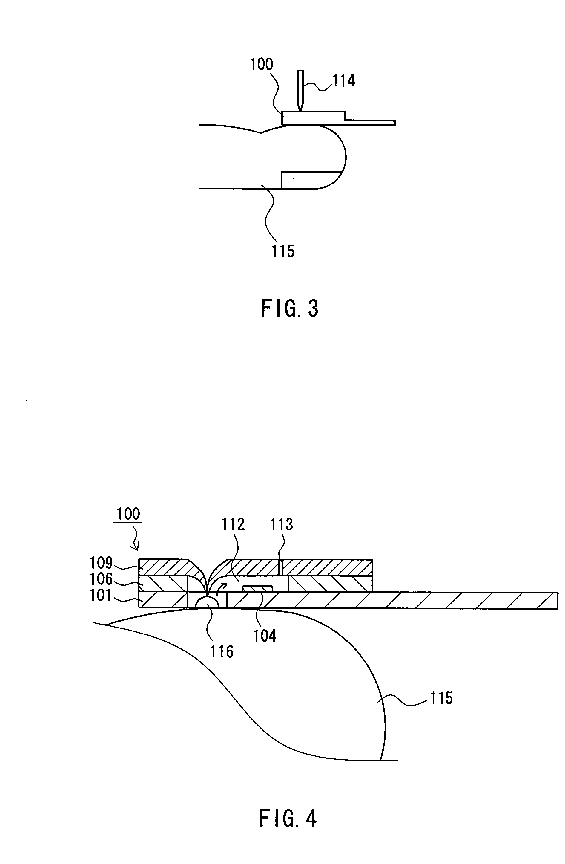
The present invention provides a sensor for blood component analysis that can reliably measure using a trace amount of blood. The sensor includes a substrate, a spacer, and a cover. The cover is placed on the substrate with the spacer in between, creating a space where blood can be collected and analyzed. The sensor has a lancing portion that allows for easy blood collection. The blood is then guided by a burr formed when the cover is broken through, ensuring that even a small amount of blood can be reliably led to the analysis portion. The sensor is also advantageous for people with poor eyesight, such as diabetics. Overall, the sensor simplifies blood collection and analysis, making it easier for anyone to measure blood components.

Problems solved by technology

Moreover, in the self-measurement of blood glucose level by diabetics, delicate operations of lancing and collecting blood have been a significant burden on diabetics whose eyesight generally is not very good.

Method used


Image

  • Sensor for blood component analysis
  • Sensor for blood component analysis
  • Sensor for blood component analysis

Examples


Embodiment Construction

[0021] In the present invention, it is preferable that a plurality of channels and analysis portions are provided with respect to one lancing portion. With this configuration, a plurality of items can be measured by performing lancing only once.

[0022] In the present invention, it is preferable that a plurality of lancing portions are provided in one sensor, and at least one channel and analysis portion are provided with respect to each lancing portion. With this configuration, one sensor can be used in a plurality of measurements.

[0023] In the present invention, it is preferable that at least the lancing portion of the cover is hydrophilic. Blood normally is hydrophilic. Thus, when the lancing portion of the cover is hydrophilic, blood can adhere well to the burr formed. Accordingly, with this configuration, blood can be supplied to the analysis portion more reliably.

[0024] In the present invention, it is preferable that an air vent hole is provided in a portion of the cover that...


PUM


Abstract

A sensor for blood component analysis, which allows even a trace amount of blood to be led to an analysis portion reliably. The sensor for blood component analysis includes a substrate, a spacer, and a cover. The cover is disposed on the substrate with the spacer intervening between the cover and the substrate, whereby a space that serves as an analysis portion and a channel for leading blood to the analysis portion is formed inside the sensor. Through holes are formed in the substrate and the spacer, respectively, so that a common through hole through which a needle of a lancet can pass is formed when the spacer is disposed on the substrate. The through hole of the spacer communicates with the channel and a top of the through hole of the spacer is covered with the cover, whereby a lancing portion is formed by the common through hole and a portion of the cover covering the top of the through hole of the spacer. In use, the sensor is placed at a position where blood collection is to be performed, the portion of the cover covering the lancing portion is broken through with the needle of the lancet so that the needle is allowed to pass through the common through hole to puncture the position, and blood that has come out is guided by a downwardly protruding burr formed when the cover is broken through so that the blood is led to the channel and flows through the channel to be led to the analysis portion.

Description

BACKGROUND OF THE INVENTION [0001] 1. Field of the Invention [0002] The present invention relates to a sensor for blood component analysis. [0003] 2. Related Background Art [0004] Conventionally, sensors for blood component analysis have been used for clinical test, self-measurement of blood glucose level by diabetics, etc. (see JP 2001-346781 A, for example). FIG. 10 shows an example of a sensor for measuring a blood glucose level. As shown in FIG. 10, in this sensor 1000, a working electrode 1002 and a counter electrode 1003 are formed on an insulating base material 1001, and a reagent layer is disposed on these electrodes, thereby forming an analysis portion 1004. The reagent layer contains an oxidoreductase (e.g., glucose oxidase), a mediator, and the like. A cover 1005 is disposed on the substrate 1001 so as to cover an entire area excluding one end portion (the end portion on the right in FIG. 10) with a spacer (not shown) intervening therebetween. The analysis portion 1004 co...

Claims


Application Information

Patent Timeline
Patent Type & Authority Applications(United States)
IPC IPC(8): A61B5/00A61B5/145A61B5/1473A61B5/15A61B5/151A61B5/157C12Q1/00G01N31/22
CPCA61B5/1411A61B5/14532A61B5/1486G01N27/3272C12Q1/005C12Q1/006A61B2562/0295A61B5/150022A61B5/150213A61B5/150343A61B5/150358A61B5/150412A61B5/150442A61B5/150572A61B5/150969
Inventor FUJIWARA, MASAKIIKEDA, SHIN
Owner PHC HLDG CORP
Learn More