Eureka AIR delivers breakthrough ideas for toughest innovation challenges, trusted by R&D personnel around the world.

Multi-function breadmaker

a breadmaker and multi-functional technology, applied in baking, baking plants, food science, etc., can solve the problems of not meeting the various demands of consumers, and achieve the effect of improving the performance-cost ratio and less components

Inactive Publication Date: 2005-06-09
WANG DONGLEI
View PDF5 Cites 23 Cited by
  • Summary
  • Abstract
  • Description
  • Claims
  • Application Information

AI Technical Summary

Benefits of technology

[0003] The main object of the present invention is to provide a multi-function breadmaker which can either work in single-pan mode or multiple-pan mode, so that the users can make bread of different size and different flavor by choosing different modes.
[0016] Since said breadmaker has multiple sets of pan assemblies which are interchangeable and are of different size, and said breadmaker can work in different modes corresponding to different set of pan assemblies, compared with conventional breadmaker, the breadmaker of the present invention has following advantages:
[0018] Since different pan assemblies can be loaded in the same breadmaker, more options are available for users. Bread of different size, shape and flavor can be produced with the same breadmaker, which provides more choices for the consumers and is more popular in market.
[0020] Since different sets of pan assemblies can be loaded in the same breadmaker, while only one set of base plate, transmission assembly and electric motor is needed, one breadmaker will have the same functions as several conventional breadmakers with less components required. Therefore, the performance-cost ratio of said breadmaker is improved.

Problems solved by technology

However, these two kinds of breadmaker can work in only one mode, and can not satisfy the various demands of the consumers.

Method used


Image

  • Multi-function breadmaker
  • Multi-function breadmaker
  • Multi-function breadmaker

Examples


Embodiment Construction

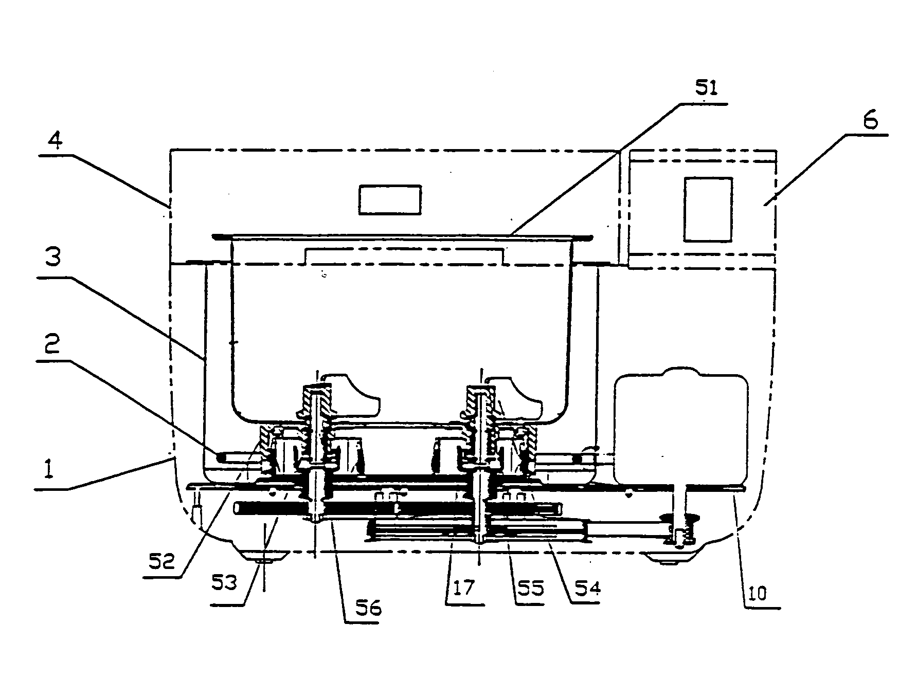
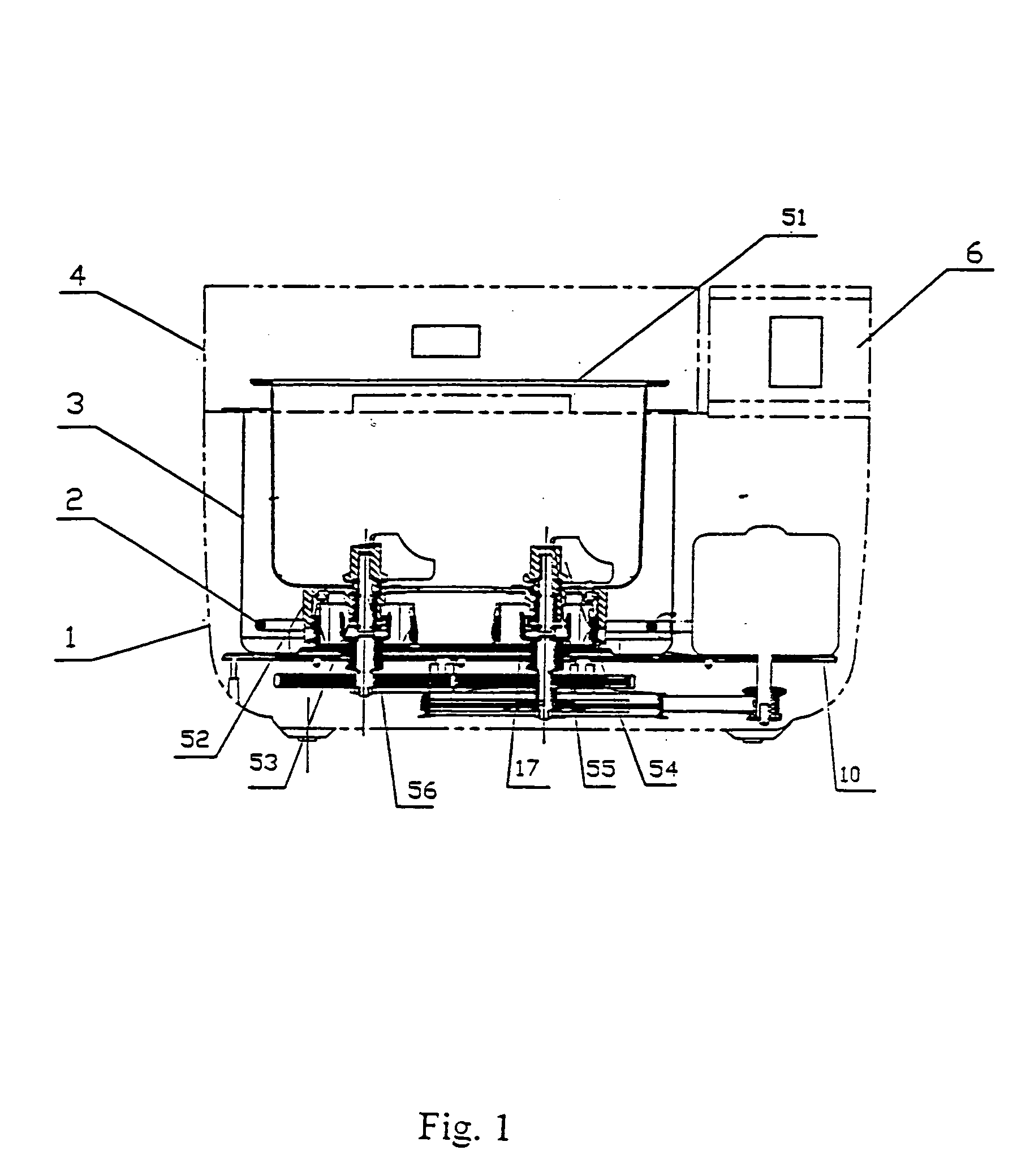
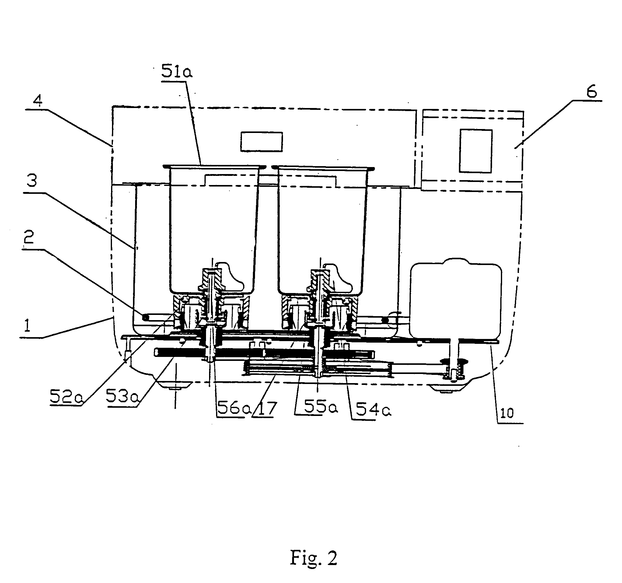
[0024] As shown in FIGS. 1, 2 and 3, in a preferred embodiment, the breadmaker comprises a housing 1, an electric heater 2, an oven chamber 3, a top cover assembly 4, a base plate 10, a control assembly 6, an electric motor 9, a transmission assembly, two driving shafts 71, 72, and two sets of pan assemblies.

[0025] The housing 1 is for accommodating and protecting the internal parts. The base plate 10 is located at the bottom within the housing 1, the oven chamber 3 and electric motor 9 are both located on the base plate 10, the transmission assembly is located below the base plate 10. Two driving shafts 71, 72 passing through the base plate 10 are installed at the bottom of the oven chamber 3, and are driven simultaneously by the electric motor 9. The pan assemblies are installed within the oven chamber 3, the electric heater 2 inside the oven chamber 3 is located at the bottom and irradiates heat for breadmaking.

[0026] The pan assemblies are for accommodating flour, kneading and...


PUM


Abstract

This invention discloses a multi-function breadmaker comprising: a housing, a base plate, an oven chamber, an electric heater, pan assemblies, a control assembly, an electric motor, a transmission assembly and multiple driving shafts; said base plate is installed at the bottom within the housing, said oven chamber and electric motor are both installed on the base plate, said transmission assembly is installed below the base plate; said multiple driving shafts, passing through the base plate, are installed at the bottom of the oven chamber, and driven simultaneously by the electric motor; characterized in that, there are at least two sets of pan assemblies, each set includes pans of different number and different size; each pan assembly includes a pan, a pan base and at least one kneading bar; each set of pan assemblies is interchangeable with another set, and can be installed on the bottom of said oven chamber, the kneading bar of each pan assembly engaging with corresponding driving shaft can be driven by said driving shaft; said control assembly includes software, whereby said breadmaker can work in different modes with corresponding set of pan assemblies loaded.

Description

TECHNICAL FIELD [0001] This invention relates to a multi-function breadmaker, and more particularly, to a breadmaker which can work in different modes. BACKGROUND OF THE INVENTION [0002] The conventional breadmaker works in single mode, either in single-pan mode, wherein the breadmaker is loaded with a single big pan (2.0 lb or 2.5 lb), or in two-pan mode, wherein the breadmaker is loaded with two small pans (1.0 lb). For example, the U.S. Pat. No. 6,113,966 entitled “Rapid Cycle Breadmaker” disclosed a breadmaker which has a single pan with two kneading bars, and only one loaf can be produced each time. While the Chinese patent No.99238752.3 entitled “A New Type of Breadmaker with Two Pans” disclosed a breadmaker which has two pan assemblies, each pan assembly including a top cover, a pan and a kneading bar. Said two pan assemblies are driven by one motor simultaneously via the transmission system. Since each pan can be loaded with different bread ingredients, the breadmaker can pr...

Claims


Application Information

Patent Timeline
IPC IPC(8): A21B7/00
CPCA21B7/005
Inventor WANG, DONGLEI
Owner WANG DONGLEI
Why Eureka
Eureka Blog
Learn More