Chain cutter

a chain cutter and chain cutting technology, applied in the field of chain cutting apparatus, can solve the problems of reducing the cutting efficiency of the chain cutter, so as to reduce the time, energy and equipment required, and the effect of reducing the physical exertion

Inactive Publication Date: 2005-06-09
VINDEE INDS
View PDF14 Cites 6 Cited by
  • Summary
  • Abstract
  • Description
  • Claims
  • Application Information

AI Technical Summary

Benefits of technology

[0010] The first shearing member has a shearing surface defining a shearing plane and terminating in a first shearing edge. The first shearing member includes a jaw. The jaw has a primary bearing surface to exert shearing and bending forces upon the chain link and a secondary bearing surface for preventing unrestrained twisting during the shearing and bending operations. The jaw defines an opening configured to accommodate the thickness of the chain link.
[0013] Significantly, the actuator system requires no priming before operation and moves the second shearing member smoothly and consistently through a substantially uniform stroke at a steady velocity.
[0014] Advantageously, the present invention provides an automated apparatus for cutting and opening in a single operation a chain link, thereby minimizing the time, energy, and equipment required. Furthermore, the apparatus is capable of cutting not only chain but also bolts, wire rope, and the like.
[0015] Advantageously, the present invention provides an automated chain cutting apparatus which is compact, powerful enough to operate on chain links of heavy—as well as light—gauge, and composed of relatively inexpensive components, to fulfill the cutting needs of retail establishments and light manufacturing facilities.
[0016] By eliminating the need to cut the chain link by manual exertion, the present invention can be used by a wide range of users and requires very little physical exertion on the part of the user. The chain cutting apparatus can be about six times as fast as a prior art manual chain cutting apparatus in cutting a chain link. Furthermore, no priming is required before operating the apparatus.

Problems solved by technology

In retail establishments selling chain and in light manufacturing facilities, chain is generally cut by either sawing through the chain links or by using a cold forming pincher-type tool commonly called a “bolt cutter.” While these techniques are adequate for cutting small gauge chains, the same techniques raise a number of practical problems in cutting larger gauge chains.
In the case of sawing through a link, the most serious problem arises from the necessity to support the chain link rigidly in a vice or other clamping apparatus while a hack saw is employed to saw through the link at a point along its circumference.
This second cutting operation is time consuming and difficult when dealing with heavy gauge chains.
Another problem arises because of the difficulty in holding the tool; namely, the risk that the cutting edges will be abused.
Moreover, sawing cable or wire rope to cut it causes fraying at the cut ends.
Cutting cable or wire rope by cold forming techniques is only effective if the working edges of the “bolt cutter” are maintained adequately to sever the individual strands of the cable.
It is often difficult to so maintain the edges when, as a result of economy, the same tool is used on chain, bolts, cable, and other like materials.
Although such a device has many desirable features and advantages, there remain certain problems with this cutter.
For example, the manual chain cutter using a manual pump jacks is prone to fluid leakage, labor intensive to operate, slow and under-powered for cutting certain sizes of chain link.
The seals in the apparatus have a tendency to wear out and allow fluid leakage to occur.
Furthermore, maintaining the manual pump jacks can be cumbersome.

Method used


Image

  • Chain cutter
  • Chain cutter
  • Chain cutter

Examples


Embodiment Construction

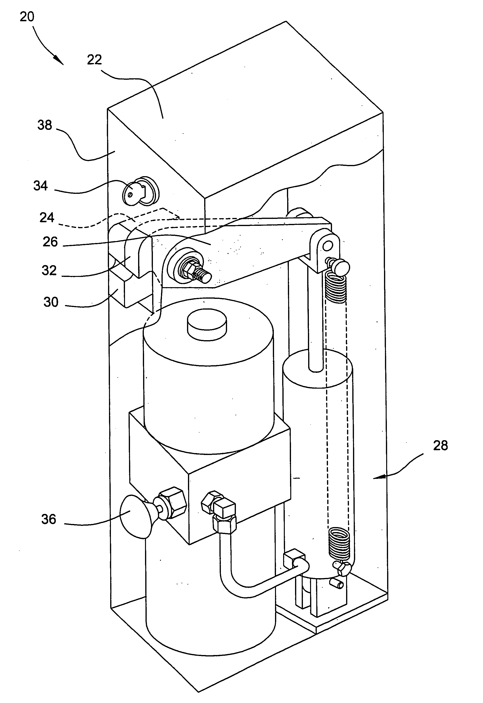
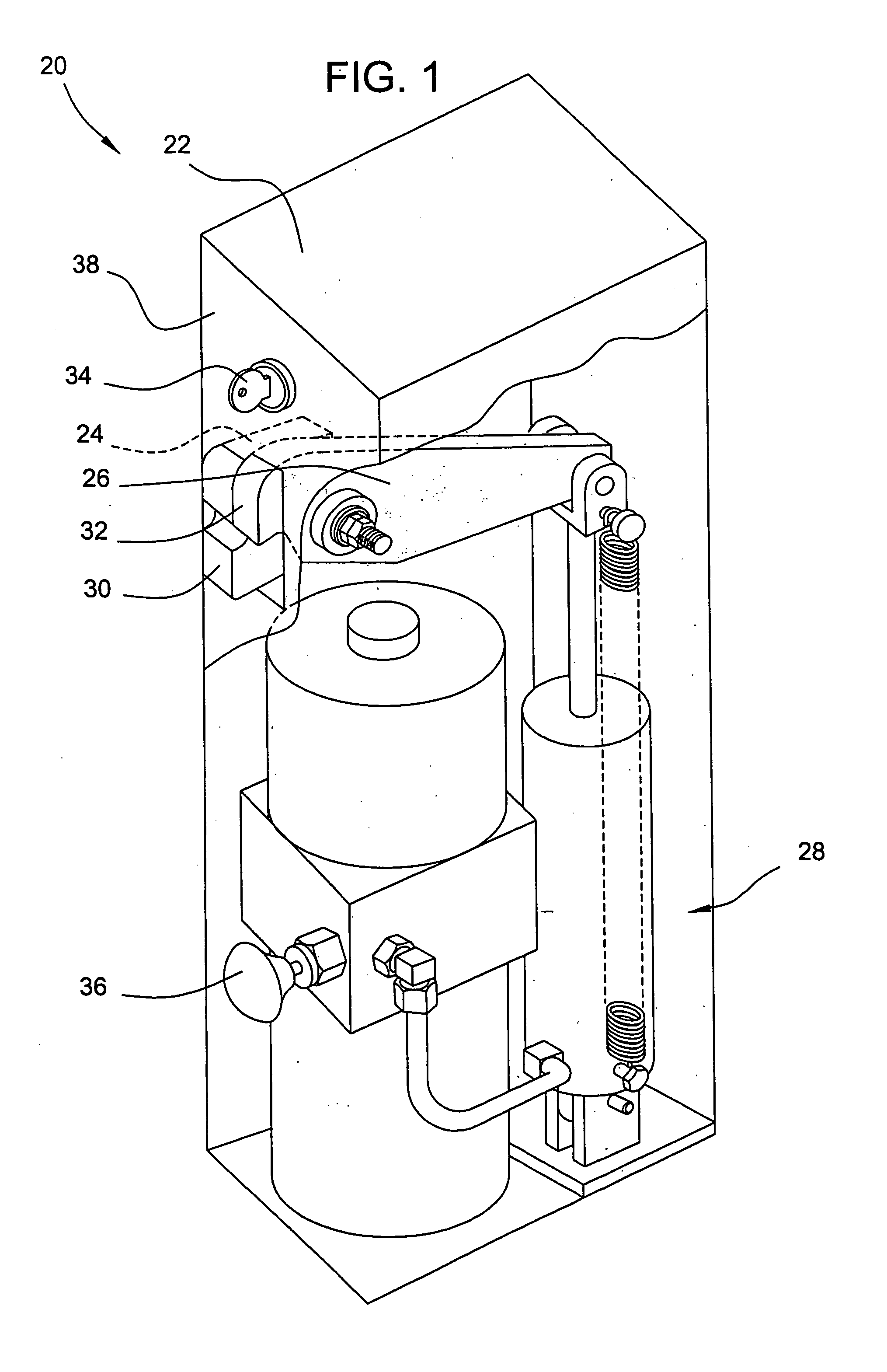
[0032] Shown in the drawings is an illustrative apparatus for cutting and opening chain links and bolts and for severing steel wire sold, for example, in hardware stores and material supply depots. The illustrative chain cutter shown herein improves upon and solves some of the drawbacks associated with the chain cutter shown and described in U.S. Pat. No. 3,996,782, filed Jul. 17, 1975, and entitled “Chain Cutting Apparatus,” which is incorporated herein in its entirety by reference.

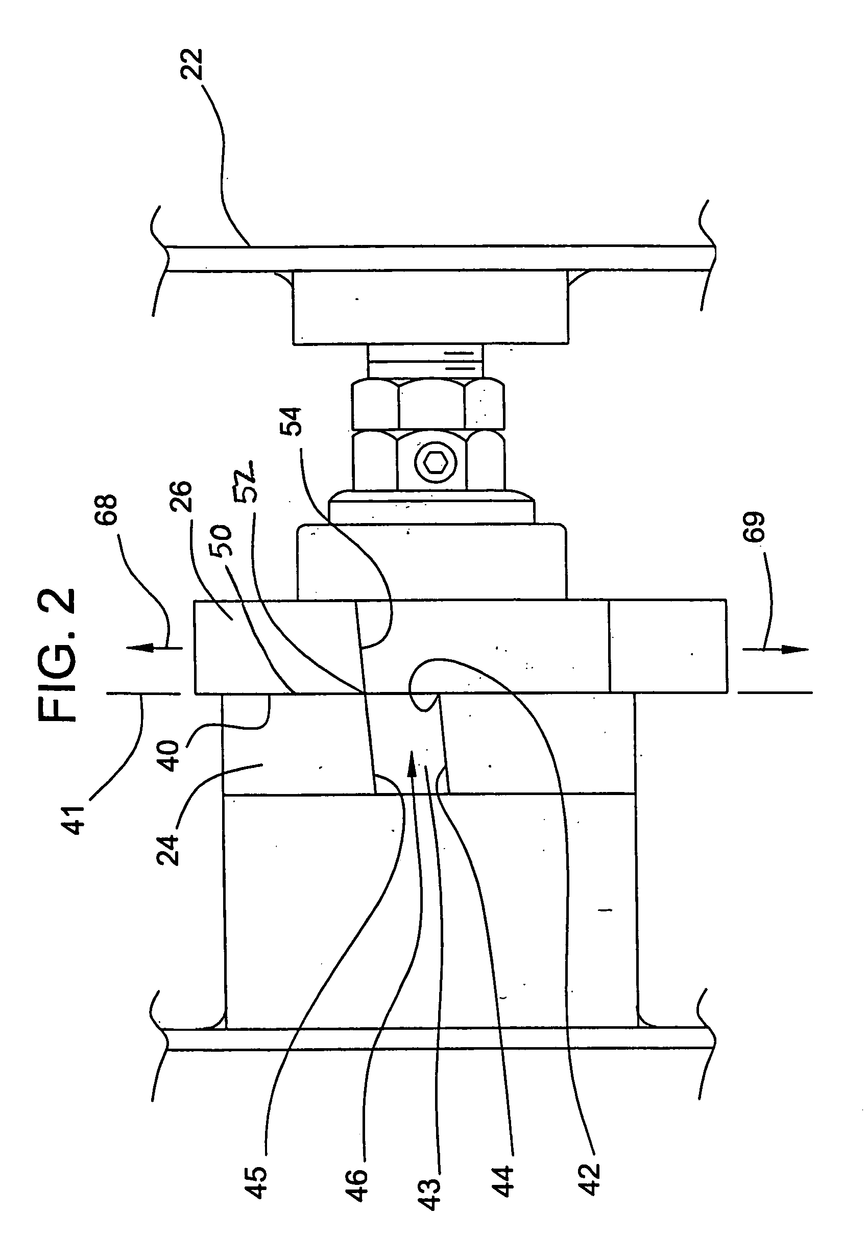
[0033] The instant apparatus employs a pair of shearing members which interact to first shear a link of chain at a point along its circumference and then to bend the link. The latter operation of opening the link to permit the disengagement of the severed link is more efficient, energy wise, than generating a second cut to facilitate removal of the link. To allow a wide range of operators to use the chain cutting apparatus, an automatic actuator system is provided to operate automatically at least one o...


PUM

PropertyMeasurementUnit
rake angleaaaaaaaaaa
jaw angleaaaaaaaaaa

Abstract

A compact chain cutting apparatus for automatically shearing and opening a chain link of a selected thickness in one operation is disclosed. The apparatus includes a housing, a first shearing member, a second shearing member, and an electro-hydraulic actuator system. The first shearing member is mounted to the housing. The second shearing member is pivotally mounted to the housing for movement to exert, in cooperation with the first shearing member, shearing and bending forces upon the chain link. The electro-hydraulic actuator system cooperates with the second shearing member to move automatically the second shearing member to shear and to bend the chain link, thereby defining an opening in the chain link greater than the thickness of the link.

Description

FIELD OF THE INVENTION [0001] The present invention relates generally to a chain cutting apparatus, and more particularly to an automatically operated, electro-hydraulically actuated apparatus for cutting and opening chain links. BACKGROUND OF THE INVENTION [0002] In retail establishments selling chain and in light manufacturing facilities, chain is generally cut by either sawing through the chain links or by using a cold forming pincher-type tool commonly called a “bolt cutter.” While these techniques are adequate for cutting small gauge chains, the same techniques raise a number of practical problems in cutting larger gauge chains. [0003] In the case of sawing through a link, the most serious problem arises from the necessity to support the chain link rigidly in a vice or other clamping apparatus while a hack saw is employed to saw through the link at a point along its circumference. If only one cut is made through the link, some means of bending the link must be employed in order...

Claims


Application Information

Patent Timeline
Patent Type & Authority Applications(United States)
IPC IPC(8): B21D31/02B21L21/00B23D17/06B23D27/06
CPCB21L21/00B23D27/06B23D17/06Y10T83/8809Y10T83/9396
Inventor MCCARTHY, ROBERT E.VERRE, JOHN L.BAKKER, DOUGLAS A.
Owner VINDEE INDS
Why Eureka
Try Eureka