
Surgical device with a moveable instrument protector

a surgical device and protector technology, applied in the field of surgical devices, can solve the problems of introducing infection in patients, affecting the cleaning effect of the device, and affecting the cleaning effect of the patient, so as to prevent inadvertent rolling of the device, facilitate cleaning of the device, and prevent over tightening

Inactive Publication Date: 2005-06-02
DIAMATRIX
View PDF41 Cites 119 Cited by
  • Summary
  • Abstract
  • Description
  • Claims
  • Application Information

AI Technical Summary

Benefits of technology

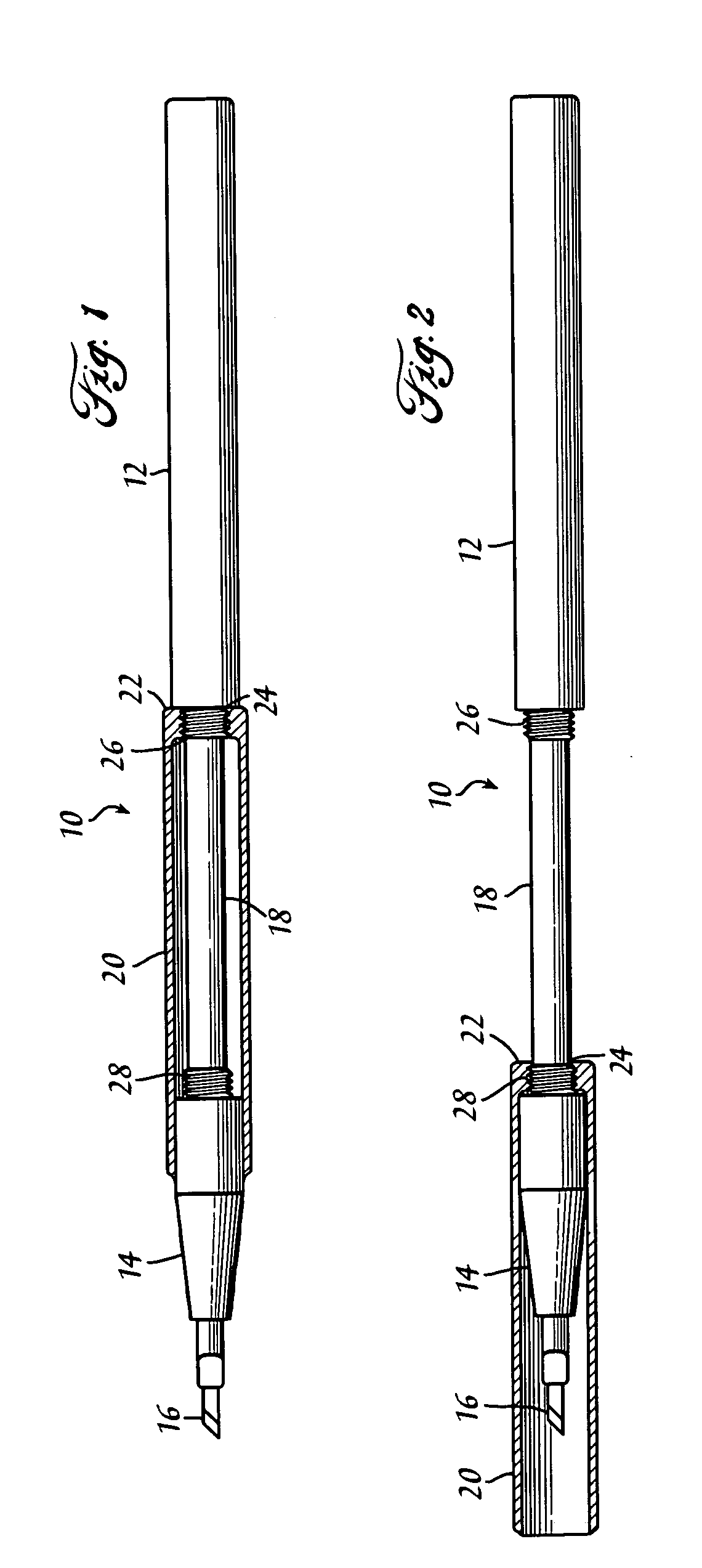
[0010] The body may be formed of one or more elements, for example, by the interconnection between the tip portion with the reduced diameter portion and the handle portion. The body of the surgical device may be a unitary member, thus reducing costs of manufacturing a multipart body.
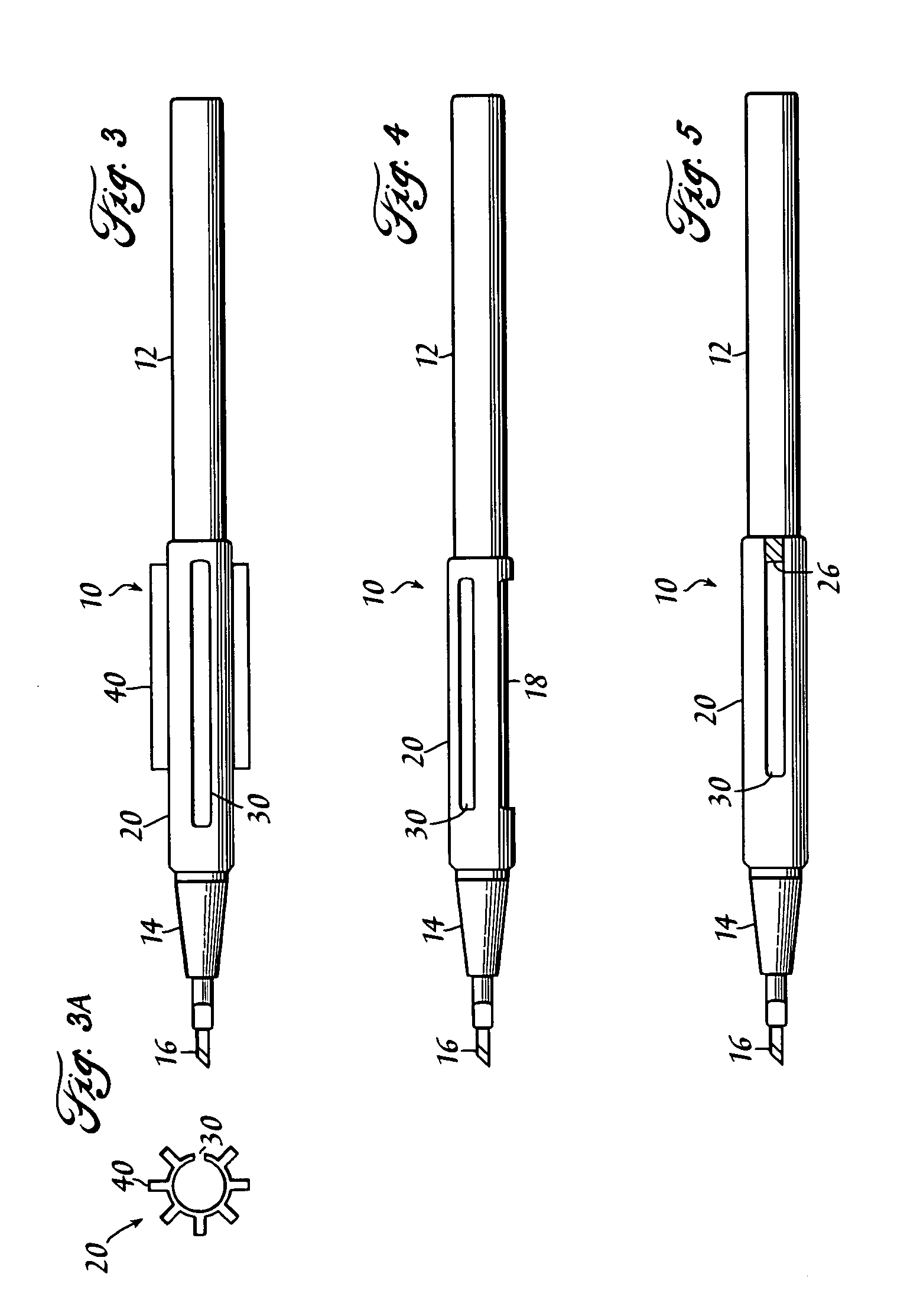
[0012] The guard or the handle may include protrusions formed on the exterior thereof to prevent inadvertent rolling of the device and / or aide in gripping the device. The guard may be sized so that the outside diameter of the guard is substantially the same as the handle portion of the body when the guard is in the open position.
[0013] The guard may include one or more slots formed between the first and the second opening continuous with the first opening. The elongated slots provide a mechanism for expanding the first opening to prevent over tightening of the guard in a locked position, for facilitating complete cleaning and sterilization of the device and to aide in placing the guard on the body. The guard may include additional openings formed through the guard to facilitate cleaning of the device.

Problems solved by technology

Surgical devices include a working end or instrument that may be delicate and / or have a sharp point or cutting edge.
The instruments can be extremely sharp, and the extreme sharpness may render them hazardous when passed back and forth during use in surgical procedures.
If the instrument has already been used on the patient, then there is a potential danger of infection since any sharp or tapered instrument can very easily cut or rip through a surgical glove and the skin beneath the glove.
Additionally, if the entire surgical device is not sterilized it may introduce infection in the patient.
While this arrangement solves some of the limitations of the prior art surgical devices, other common limitations still exist.

Method used


Image

  • Surgical device with a moveable instrument protector
  • Surgical device with a moveable instrument protector
  • Surgical device with a moveable instrument protector

Examples


Embodiment Construction

[0028] Refer now to the drawings wherein depicted elements are not necessarily shown to scale and wherein like or similar elements are designated by the same reference numeral through the several views.

[0029] As mentioned above, many reusable surgical devices include at least one generally cylindrical handle with a distal end that carries an instrument for performing a medical procedure. Surgical knives, as more fully described below in accordance with preferred embodiments of the present invention, are typical of such reusable surgical devices. Although a surgical knife is illustrated in this specification, those skilled in the art will readily appreciate that the instant invention includes all surgical devices and the instrument that is carried.

[0030]FIG. 1 is a partial cross-section view of a surgical device of the present invention. The surgical device includes a body 10 carrying an instrument 16 and a protective guard 20. Body 10 includes a generally cylindrical handle portio...


PUM


Abstract

A surgical device having an instrument connected to a handle with a substantially cylindrical guard moveable between an open position exposing the instrument for use and a closed position substantially covering the instrument. The guard having at least one opening formed through a wall and extending substantially to or continuous with an end wall opening.

Description

RELATED APPLICATIONS [0001] This application is a continuation of application Ser. No. 10 / 016,984 entitled Protection System for Surgical Instruments, filed on Dec. 7, 2001, which is incorporated herein by reference.FIELD OF THE INVENTION [0002] The present invention relates in general to surgical devices and more particularly to a surgical device having a protector moveable between an open position exposing an instrument and a closed position covering the instrument. BACKGROUND [0003] Surgical devices include a working end or instrument that may be delicate and / or have a sharp point or cutting edge. Examples of such instruments include scalpels, blades, hooks (such as Sinskey hooks, Bonn hooks, insertion hooks, twist hooks and the like), scissors (such as retinal scissors and the like), picks (such as retinal picks and the like), forceps, probes, lens manipulators, markers, collar buttons, choppers, cystotomes irrigation needles and cannulas, spatulas (such as Castroviejo spatulas ...

Claims


Application Information

Patent Timeline
Patent Type & Authority Applications(United States)
IPC IPC(8): A61B17/32A61B19/00
CPCA61B17/3211A61B2019/4868A61B2019/4805A61B2017/32113A61B2090/0801A61B2090/0813
Inventor DYKES, RONALD E.
Owner DIAMATRIX
Learn More