
Power measurement system comprising PC and voltage meter

a power measurement and voltage meter technology, applied in the direction of transmission monitoring, receiver monitoring, electrical equipment, etc., can solve the problems of increasing the cost of assembly line establishment, and a power meter for measuring power may cost more than us$15,000, etc., to eliminate the cost of buying, easy maintenance, and simple operation

Inactive Publication Date: 2005-06-02
D-LINK
View PDF2 Cites 0 Cited by
  • Summary
  • Abstract
  • Description
  • Claims
  • Application Information

AI Technical Summary

Benefits of technology

[0005] A primary object of the present invention is to provide a power measurement system comprising a PC and a voltage meter. The inexpensive power measurement system has advantages of simple operation, easy maintenance, eliminating the cost of buying many expensive equipment for testing a wireless communication product in the automatic production line, and significantly increasing the competitiveness of the wireless communication products in the market. Further, by utilizing the present invention, the above drawbacks of the prior art such as expensive power meters and high manufacturing cost of the wireless communication products can be overcome.

Problems solved by technology

Typically, a power meter for measuring power may cost more than US$15,000.
As such, the establishment of a number of power test stations in several assembly lines may cost at least US$300,000.
This will inevitably greatly increase the cost of the establishment of assembly lines.
This has the drawback of delaying the normal delivery time if orders more than the normal production are received unexpectedly since all available assembly lines are full.

Method used


Image

  • Power measurement system comprising PC and voltage meter
  • Power measurement system comprising PC and voltage meter

Examples


Embodiment Construction

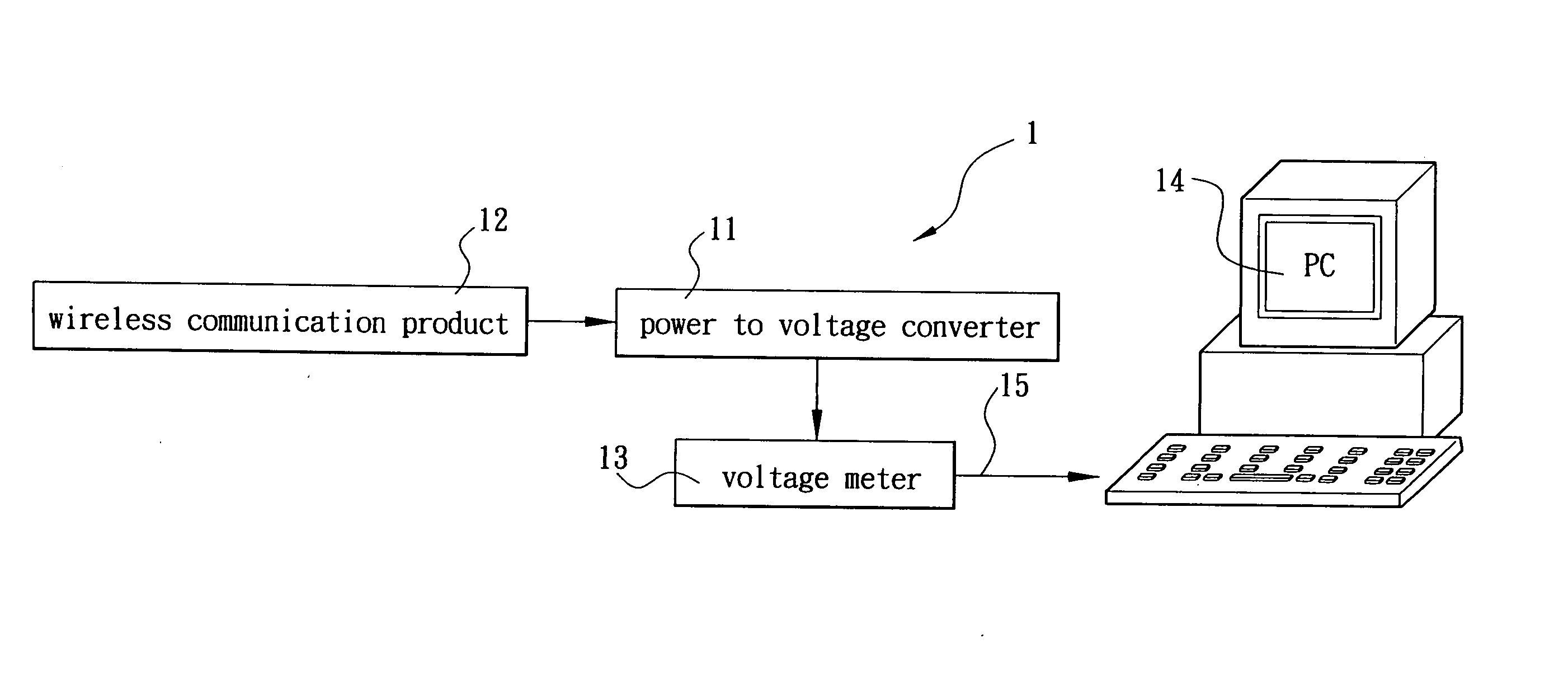
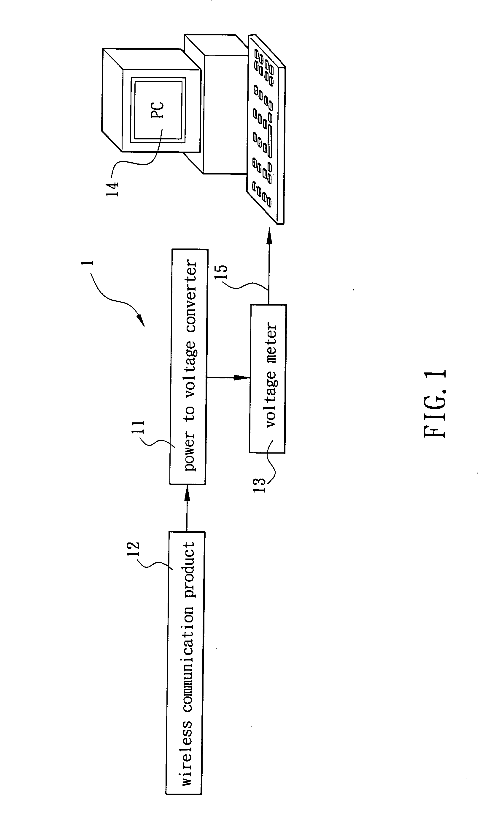
[0010] Referring to FIG. 1, there is shown a power measurement system 1 in accordance with the invention. The power measurement system 1 comprises a power to voltage converter 11 for receiving input signals from a wireless communication product 12 to be tested and converting the input signals into voltage signals, and a voltage meter 13 for measuring a voltage value of the voltage signals. Hence, the invention simply further comprises a PC 14 for reading the measured voltage value of the voltage meter 13 via an interconnected communication interface 15 and converting the read voltage value into an actual power based on a created calibration table. As an end, a correct power measurement is obtained.

[0011] Again referring to FIG. 1, while the calibration table being created, a power meter (not shown) coupled to the PC 14 via an interface (such as a RS-232 interface) is used to measure the actual output power of each of a plurality of channels of one of a certain series of wireless co...


PUM


Abstract

The present invention is to provide a power measurement system comprising a PC and a voltage meter, which comprises a power to voltage converter to receive input signals from a wireless communication product to be tested and convert the input signals into voltage signals, a voltage meter to measure a voltage value of the voltage signals, and a PC to read the measured voltage value of the voltage meter and convert the read voltage value into an actual power based on a created calibration table. As an end, a correct power measurement is obtained.

Description

FIELD OF THE INVENTION [0001] The present invention relates to power measurement and more particularly to an improved power measurement system comprising a PC (personal computer) and a voltage meter. BACKGROUND OF THE INVENTION [0002] The Internet, particularly WWW (World Wide Web) thereof, has known a rapid, spectacular development in recent years. WWW is used to provide a variety of multimedia services including voice, graphics, dynamic images, etc. in addition to a conventional e-mail service. Thus, a substantial amount of data is accompanied with the multimedia services. Hence, various network communication products having high performance are commercially available in which wireless communication products are the most popular ones among the market. [0003] For designing and producing quality wireless communication products and ensuring that bandwidth occupied by the communication product is complied with the specifications, typically, an employee of a wireless communication prod...

Claims


Application Information

Patent Timeline
Patent Type & Authority Applications(United States)
IPC IPC(8): H04B17/00H04W24/00
CPCH04W24/00H04B17/318H04B17/21
Inventor YANG, KUEI-CHI
Owner D-LINK
Learn More