
Methods and systems for providing a visualization graph

Active Publication Date: 2005-05-26
SAP AG
View PDF54 Cites 28 Cited by
  • Summary
  • Abstract
  • Description
  • Claims
  • Application Information

AI Technical Summary

Benefits of technology

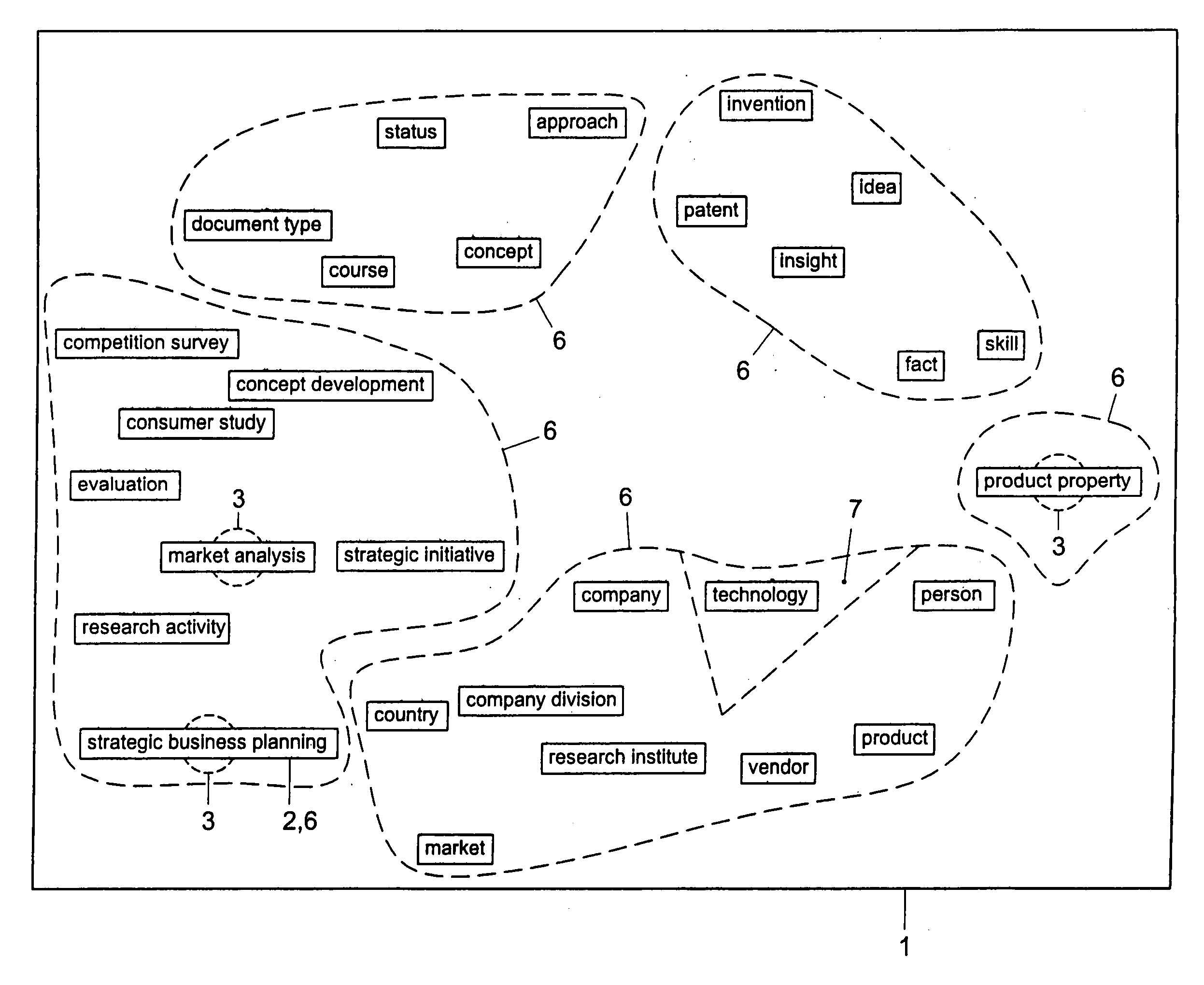
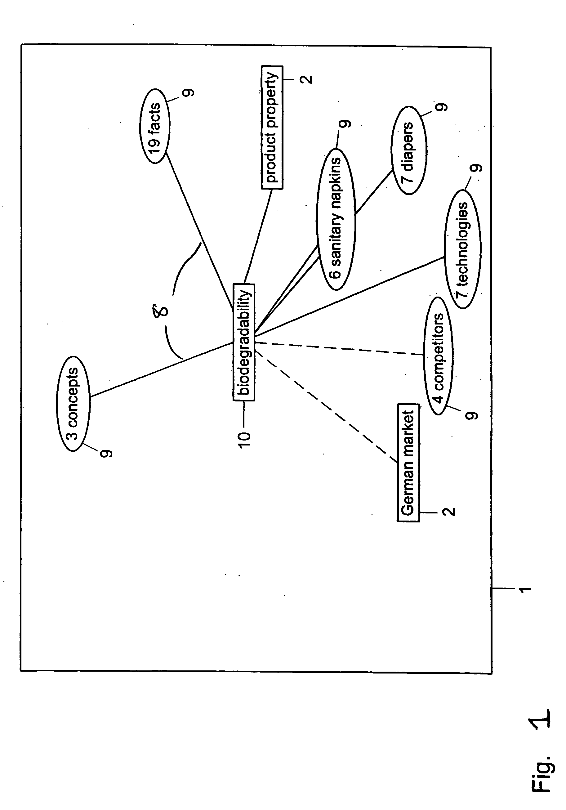
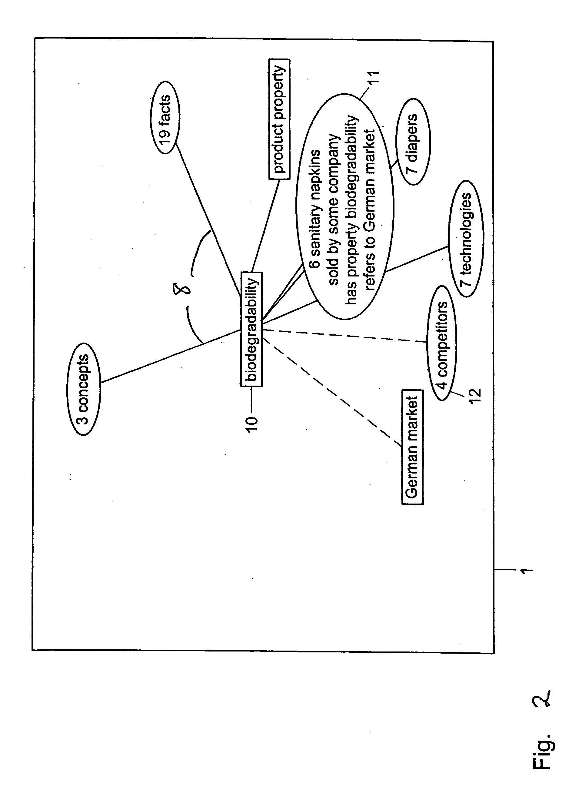
[0009] By providing the possibility to explode such groups (i.e. to display all group entities as separate nodes in the graph) by double-clicking and to put them back into the group again, links between nodes representing relations are kept to a minimum which optimizes the energy in the graph. Further, it becomes easier for the user to orientate within the graph, thus, improving his navigation of the information represented in the graph.

Problems solved by technology

However, conventional visualization graphs suffer drawbacks.
One problem with conventional visualization graphs is that when changes in the graphs are initiated, for example, when a node is double clicked on in order to include further entities related to that node into the graph, using conventional repulsion based simulation approached (which are indeterministic), a problem arises in making room for the entities of the group.
In particular, if a node placed close to a second node is “exploded”, the repulsion between the entities is so great that the system takes an unacceptable duration to converge.
Thus, the user is faced with a graph that is slow to navigate.

Method used


Image

  • Methods and systems for providing a visualization graph
  • Methods and systems for providing a visualization graph
  • Methods and systems for providing a visualization graph

Examples


Embodiment Construction

[0019] The following detailed description refers to the accompanying drawings. Wherever possible, the same reference numbers are used in the drawings and the following description to refer to the same or similar parts. While several exemplary embodiments and features of the invention are described herein, modifications, adaptations and other implementations are possible, without departing from the spirit and scope of the invention. For example, substitutions, additions or modifications may be made to the components illustrated in the drawings, and the exemplary methods described herein may be modified by substituting, reordering or adding steps to the disclosed methods. Accordingly, the following detailed description does not limit the invention. Instead, the proper scope of the invention is defined by the appended claims.

[0020]FIGS. 1-8 show visualization graphs according to examples of embodiments of the present invention. FIG. 7 shows details of a visualization graph 1 wherein a...


PUM


Abstract

A visualization graph is provided on a computer. Data corresponding to a plurality of entities is stored, wherein a semantic net includes the entities and wherein the entities are linked to each other by a plurality of relations. In response to a query with respect to an entity selected from the plurality of entities, providing a visualization graph representing the results of the query, representing a plurality of entities having a common relation as a first node on the visualization graph. In response to a predetermined stimulus causing the entities comprised at the first node to be displayed, and in response to a further predetermined stimulus causing the graph to restructure so that the node replaces the displayed entities.

Description

[0001] This application is based upon and claims the benefit of priority from prior patent application EP 03077697.5, filed Aug. 29, 2003, and prior patent application EP 03078583.6, filed Nov. 14, 2003, the entire contents of each which are expressly incorporated herein by reference. BACKGROUND [0002] I. Technical Field [0003] The present invention relates to a methods and systems for providing a visualization graph on a computer. [0004] II. Background Information [0005] Visualization graphs are tools that allow data to be handled and displayed on a display device according to certain criteria. The primary objective of navigation graphs is to display systems of complex interrelationships between entities, such as in a database or on the World Wide Web. Visualization graphs can be based on a semantic net including all entity types that occur where the considered entities are linked to each other by various kinds of relations. A visualization graph represents entities as boxes, often...

Claims


Application Information

Patent Timeline
IPC IPC(8): G06F3/14G06F3/048G06F3/0484G06F17/30
CPCG06F17/30991G06F16/9038
Inventor BERINGER, JOERGWERNER, HORST
Owner SAP AG
Learn More