
Semi-static distribution technique

a distribution technique and semi-static technology, applied in memory systems, redundant data error correction, instruments, etc., can solve the problems of increasing the fraction of disks that cannot be used for read operations, reducing the number of group sizes, and parity disks to seek, so as to improve the performance of disk-bound configuration

Active Publication Date: 2005-05-26
NETWORK APPLIANCE INC
View PDF57 Cites 1372 Cited by
  • Summary
  • Abstract
  • Description
  • Claims
  • Application Information

AI Technical Summary

Benefits of technology

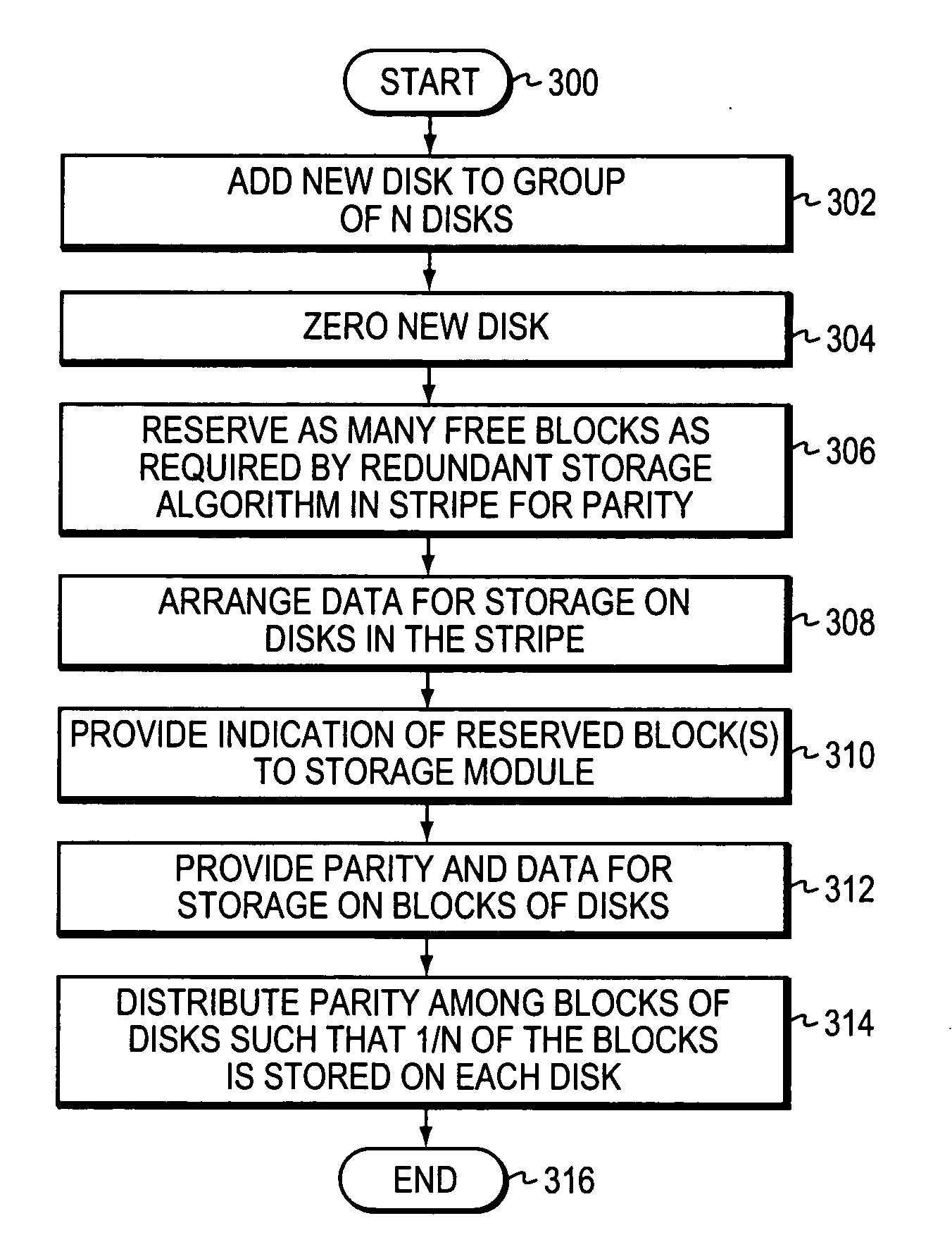
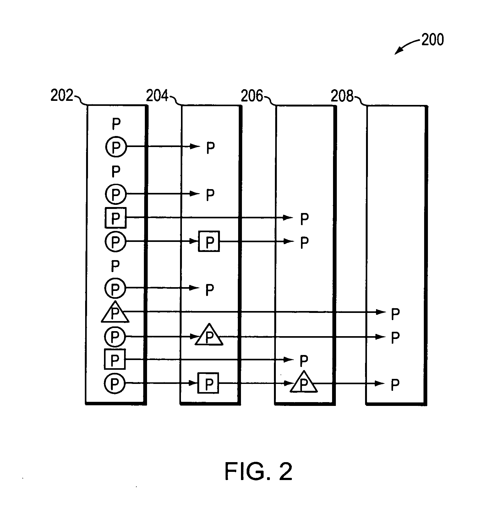
[0016] Advantageously, semi-static distribution allows those blocks that hold parity (in the stripe) to change when disks are added to the array. Reassignment occurs among blocks of a stripe to rebalance parity to avoid the case where a disk with a preponderance of parity gets “hot”, i.e., more heavily utilized than other disks, during write traffic. The novel distribution technique applies to single disk failure correction and can be extended to apply to double (or greater) disk loss protection. In addition, the semi-static distribution technique has the potential to improve performance in disk-bound configurations while retaining the capability to add disks to a volume one or more disks at a time.

Problems solved by technology

Such static file systems tend to scatter write data across many stripes in the disk array, causing the parity disks to seek for each stripe written.
Although this effect is insignificant for large RAID group sizes, those group sizes have been decreasing because of, e.g., a limited number of available disks or increasing reconstruction times of larger disks.
But this increases the fraction of disks unavailable to service read operations in a RAID-4 configuration.
The use of a RAID-4 level implementation may therefore result in significant loss of read operations per second.
Second, when a new disk is added to a full volume, the write anywhere file system tends to direct most of the write data traffic to the new disk, which is where most of the free space is located.
Repositioning of the parity information typically requires use of a complex (and costly) parity block redistribution scheme that “sweeps-through” the old and new disks, copying both parity and data blocks to conform to the new distribution.
Yet, the use of small RAID groups translates to high parity overhead, whereas the use of larger RAID groups means having a high-cost for incremental capacity.

Method used


Image

  • Semi-static distribution technique
  • Semi-static distribution technique
  • Semi-static distribution technique

Examples


Embodiment Construction

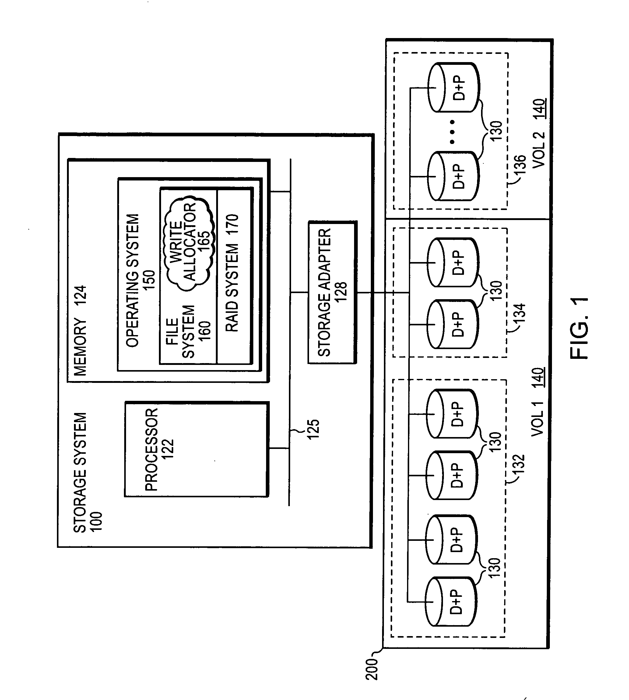
[0022]FIG. 1 is a schematic block diagram of a storage system 100 that may be advantageously used with the present invention. In the illustrative embodiment, the storage system 100 comprises a processor 122, a memory 124 and a storage adapter 128 interconnected by a system bus 125. The memory 124 comprises storage locations that are addressable by the processor and adapter for storing software program code and data structures associated with the present invention. The processor and adapter may, in turn, comprise processing elements and / or logic circuitry configured to execute the software code and manipulate the data structures. It will be apparent to those skilled in the art that other processing and memory means, including various computer readable media, may be used for storing and executing program instructions pertaining to the inventive technique described herein.

[0023] A storage operating system 150, portions of which are typically resident in memory and executed by the proc...


PUM


Abstract

A semi-static distribution technique distributes parity across disks of an array. According to the technique, parity is distributed (assigned) across the disks of the array in a manner that maintains a fixed pattern of parity blocks among the stripes of the disks. When one or more disks are added to the array, the semi-static technique redistributes parity in a way that does not require recalculation of parity or moving of any data blocks. Notably, the parity information is not actually moved; the technique merely involves a change in the assignment (or reservation) for some of the parity blocks of each pre-existing disk to the newly added disk.

Description

FIELD OF THE INVENTION [0001] The present invention relates to arrays of storage systems and, more specifically, to a system that efficiently assigns parity blocks within storage devices of a storage array. BACKGROUND OF THE INVENTION [0002] A storage system typically comprises one or more storage devices into which information may be entered, and from which information may be obtained, as desired. The storage system includes a storage operating system that functionally organizes the system by, inter alia, invoking storage operations in support of a storage service implemented by the system. The storage system may be implemented in accordance with a variety of storage architectures including, but not limited to, a network-attached storage environment, a storage area network and a disk assembly directly attached to a client or host computer. The storage devices are typically disk drives organized as a disk array, wherein the term “disk” commonly describes a self-contained rotating ma...

Claims


Application Information

Patent Timeline
IPC IPC(8): G06F11/10
CPCG06F11/1096G06F11/10G06F11/00
Inventor CORBETT, PETER F.KLEIMAN, STEVEN R.ENGLISH, ROBERT M.
Owner NETWORK APPLIANCE INC
Learn More