Heat pump type hot water supply device

a technology of hot water supply device and heat pump, which is applied in the direction of domestic hot water supply system, lighting and heating apparatus, heating types, etc., can solve the problems of increasing power consumption, low temperature of hot water to be supplied to the kitchen or the bathroom, etc., to prevent any decrease in the temperature of hot water, prevent any freezing, and perform stably

Inactive Publication Date: 2005-05-26
DAIKIN IND LTD
View PDF3 Cites 16 Cited by
  • Summary
  • Abstract
  • Description
  • Claims
  • Application Information

AI Technical Summary

Benefits of technology

[0012] In other words, in the case where there is a fear of freezing, it is possible to prevent any freezing since the water through the circulating path 12 is circulated. At this time, the water through the circulating path 12 is returned onto the bottom side of the hot water reservoir tank, so that the water of a low temperature cannot be mixed with the hot water of a high temperature reserved at the upper portion of the hot water reservoir tank 3, thereby preventing any decrease in temperature of the hot water to be used.
[0041] In the heat pump type hot water supplying apparatus of the tenth aspect of the present invention, the freeze-proof operation refers to the temperatures of the water on the fore and rear sides of the heat exchanging path of the circulating path. Consequently, it is possible to more stably perform the freeze-proof operation even if there is the fear of freezing.

Problems solved by technology

As a consequence, the hot water to be supplied to the kitchen or the bathroom becomes low in temperature.
In view of this, it has been necessary to perform the boiling operation for driving the compressor, thereby requiring excessive input energy for the purpose of the freeze-proofing, so as to cause an increase in power consumption.

Method used


Image

  • Heat pump type hot water supply device
  • Heat pump type hot water supply device
  • Heat pump type hot water supply device

Examples


Embodiment Construction

[0047] A heat pump type hot water supplying apparatus in a preferred embodiment according to the present invention will be specifically described below in reference to the accompanying drawings.

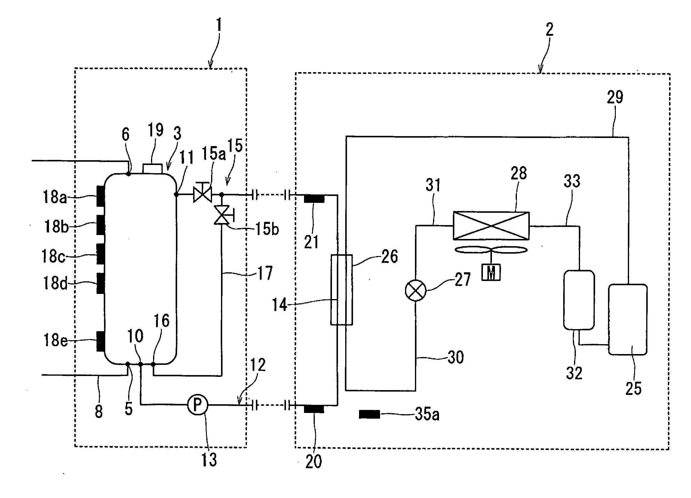
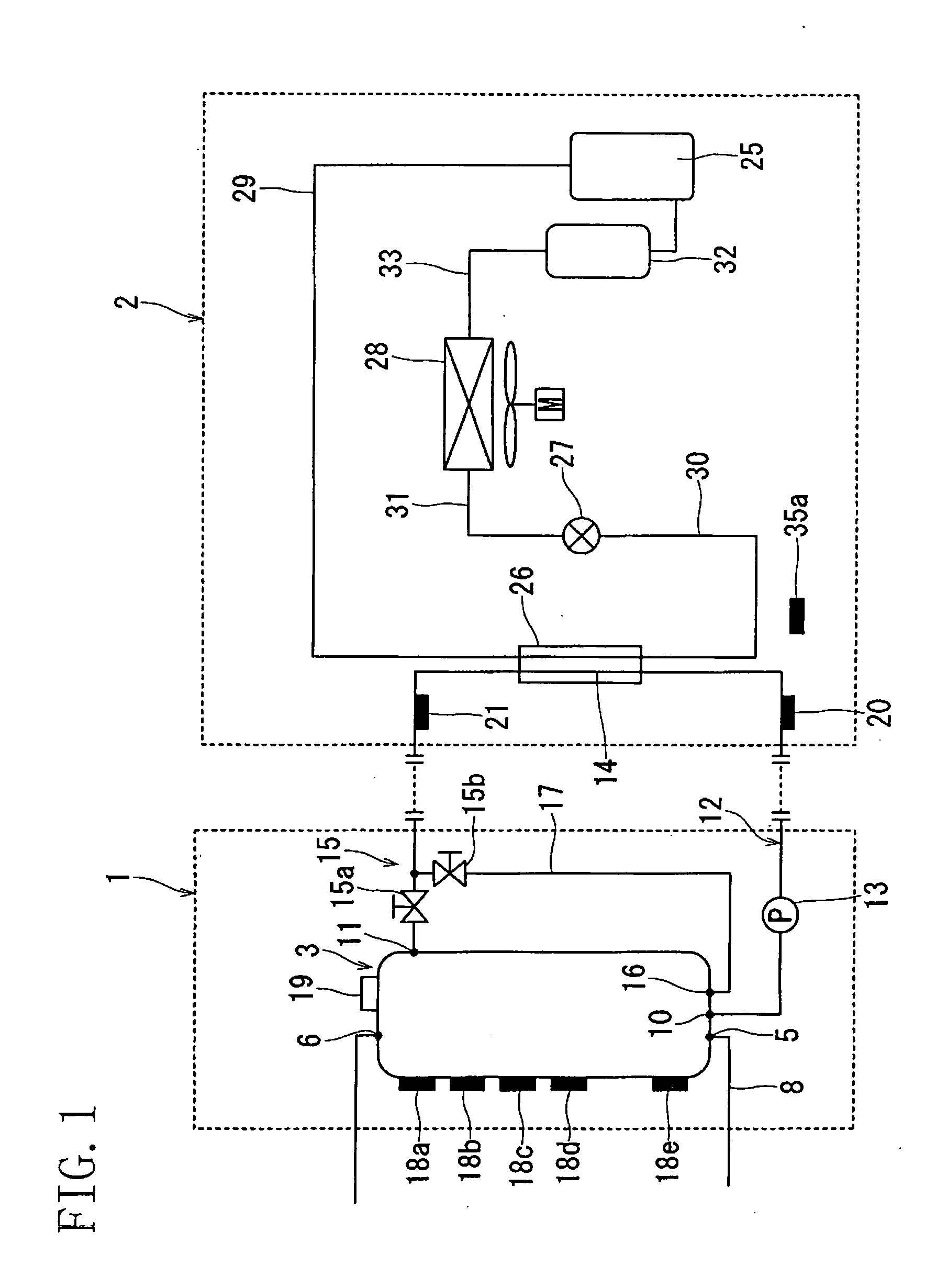
[0048]FIG. 1 is a schematic view showing a heat pump type hot water supplying apparatus in a preferred embodiment according to the present invention. The heat pump type hot water supplying apparatus is provided with a tank unit 1 and a heat source unit (i.e., a heat pump unit) 2, for heating water (hot water) reserved in the tank unit 1 by the use of the heat source unit 2.

[0049] The tank unit 1 includes a hot water reservoir tank 3. Hot water reserved in the hot water reservoir tank 3 is supplied to a bath or the like, although its illustration is omitted. Specifically, in the hot water reservoir tank 3, a water supplying port 5 is formed on the bottom wall and a hot water outlet 6 is formed on the upper wall. The water is supplied to the hot water reservoir tank 3 through the water supply...


PUM


Abstract

A heat pump type hot water supplying apparatus includes a hot water reservoir tank (3) and a circulating path (12) for connecting a water intake port (10) formed at the bottom of the hot water reservoir tank (3) and a hot water inlet (11) formed at the upper portion of the hot water reservoir tank (3) to each other. A water circulating pump (13) and a heat exchanging path (14) are disposed on the circulating path (12). A boiling operation is performed for heating the heat exchanging path (14) by a heat pump type heating source, boiling water which has not been heated yet from the water intake port (10) and returning the heated water to the hot water inlet (11). A bypassing path (17) branched from the hot water inlet (11) and connected to the bottom of the hot water reservoir tank (3) is disposed on the circulating path (12). A freeze-proof operation by circulation is performed such that the water circulating pump (13) is driven and the water reserved in the hot water reservoir tank (3) is returned to the hot water reservoir tank (3) via the bypassing path (17).

Description

TECHNICAL FIELD [0001] The present invention relates to a heat pump type hot water supplying apparatus. BACKGROUND ART [0002] As shown in FIG. 5, a heat pump type hot water supplying apparatus is generally provided with a tank unit 52 including a hot water reservoir tank 51 and a heat pump unit 54 including a water heat exchanger 53. A water intake port 55 formed at the bottom of the hot water reservoir tank 51 and a hot water inlet 56 formed at the upper portion of the hot water reservoir tank 51 are connected to each other through a circulating path 57, on which a water circulating pump 58 and a heat exchanging path 59 are disposed. In this case, the water heat exchanger 53 constitutes the heat exchanging path 59, which is heated by a heat pump type heating source. Specifically, a boiling operation is performed such that the water circulating pump 58 is driven, water which has not been heated yet is boiled by the heat exchanging path 59, and then, the heated water is returned to t...

Claims


Application Information

Patent Timeline
Patent Type & Authority Applications(United States)
IPC IPC(8): F24H1/00F24D17/02
CPCF24D17/02
Inventor CHIDA, KOUJISAKAMOTO, SHINICHI
Owner DAIKIN IND LTD
Why Eureka
Try Eureka