
Transmission power control method and transmission power control apparatus in OFDM-CDMA

a technology of transmission power control and transmission power, which is applied in the direction of power management, digital transmission, electrical equipment, etc., can solve the problems of reducing the orthogonality of channelization codes, affecting communication quality, and affecting communication quality, so as to prevent the degradation of communication quality

Inactive Publication Date: 2005-05-19
FUJITSU LTD
View PDF16 Cites 45 Cited by
  • Summary
  • Abstract
  • Description
  • Claims
  • Application Information

AI Technical Summary

Benefits of technology

The present invention provides a transmission power control method and apparatus in an OFDM-CDMA system that can maintain orthogonality of channelization codes and prevent degradation of communication quality. The method involves dividing a subcarrier band into multiple subcarrier blocks, assigning an identical transmission power to each subcarrier in each block, and controlling transmission power from one block to another. The first method includes controlling transmission power based on the total transmission power and a value obtained by dividing interference power by the propagation path, while the second method controls transmission power to render constant the ratio of average receive-signal power to interference power. These methods ensure that the orthogonality of channelization codes is maintained and communication quality is not compromised.

Problems solved by technology

However, if such subcarrier-to-subcarrier transmission power control is applied to an OFDM-CDMA communication system, the orthogonality of channelization codes declines and so does quality.
Thus, when it is attempted to apply a conventional scheme in which control of power is performed subcarrier by subcarrier to an OFDM-CDMA system, this degrades orthogonality of the channelization codes and, as a consequence, this invites a decline in communication quality.

Method used


Image

  • Transmission power control method and transmission power control apparatus in OFDM-CDMA
  • Transmission power control method and transmission power control apparatus in OFDM-CDMA
  • Transmission power control method and transmission power control apparatus in OFDM-CDMA

Examples


first embodiment

[0065] (A) First Embodiment

[0066] Structure of Base Station

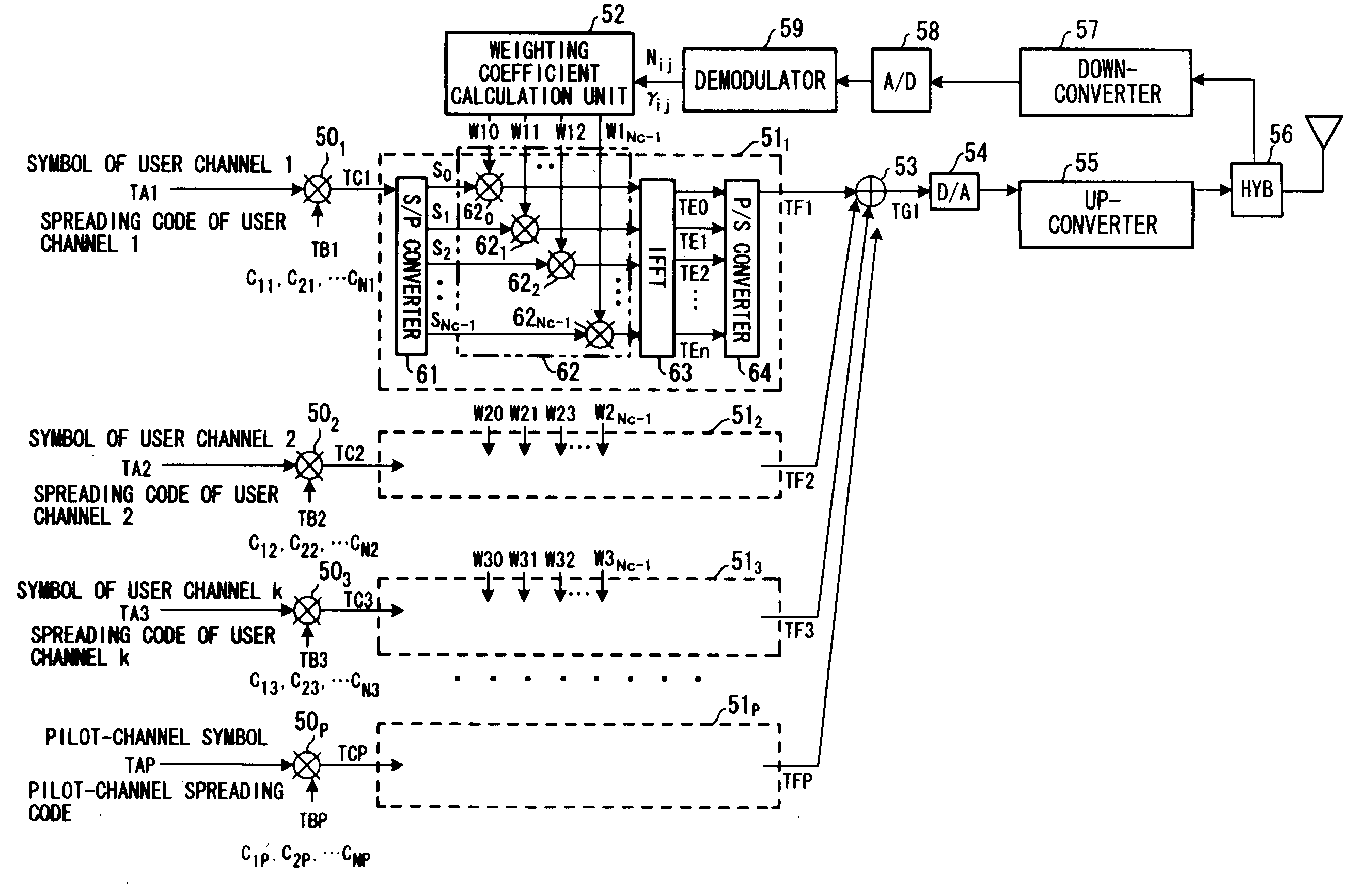
[0067]FIG. 1 is a diagram illustrating the structure of a base station in an OFDM-CDMA communication system according to a first embodiment. Transmit data of each user channel and pilot channel has been converted to a complex baseband signal (symbol) comprising an in-phase component and a quadrature-phase component.

[0068] A spreader 501 for the first user (first channel) multiplies each symbol TA1 of the first user by a channelization code TB1 (C11, C21, . . . , CN1) of the first user and outputs encoded data TC1. The channelization code TB1 has a chip rate that is SF times the symbol rate, where SF is the spreading factor and SF=N holds.

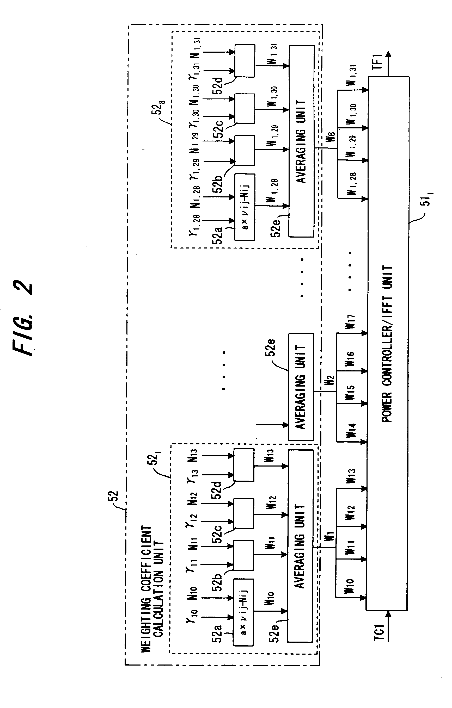
[0069] An S / P converter 61 of a power controller / IFFT unit 511 subjects M symbol's worth of N×M chip sequences to an S / P conversion. For example, if M=8, N=4 holds, the S / P converter converts 32 (=8×4) chips to parallel data S0 to SNc-1 (Nc=N×M) and outputs the parallel data. That is, the...

second embodiment

[0109] (B) Second Embodiment

[0110] In the first embodiment, weighting coefficients W1 to WM of the subcarrier blocks are calculated by the base station. In a second embodiment, the weighting coefficients W1 to WM are calculated on the side of the mobile station and are sent to the side of the base station so that transmission power control is performed for every subcarrier block.

[0111]FIG. 8 is a diagram showing the structure of a base station according to the second embodiment. Components identical with those of the first embodiment are designated by like reference characters. This differs from the first embodiment in that a weighting coefficient distribution unit 91 is provided instead of the weighting coefficient calculation unit 52. The weighting coefficient distribution unit 91 decides the weighting coefficients W1j (j=0 to Nc-1) of each subcarrier in accordance with Equation (1) using weighting coefficients W1 to WM that have been sent from the receiving side and inputs these...

third embodiment

[0113] (C) Third Embodiment

[0114] In the first embodiment, weighting coefficients W1 to WM of the subcarrier blocks are calculated by the base station. In a third embodiment, the weighting coefficients W1 to WM are calculated on the side of the mobile station, the calculated weighting coefficients W1 to WM are compared with present weighting coefficients W1 to WM, a increase / decrease in the weighting coefficients is decided and an UP / DN command is sent to the side of the base station so that transmission power control is performed for every subcarrier block.

[0115]FIG. 10 is a diagram showing the structure of a base station according to the third embodiment. Components identical with those of the first embodiment are designated by like reference characters. This differs from the first embodiment in that a weighting coefficient increase / decrease unit 100 is provided instead of the weighting coefficient calculation unit 52. Since the weighting coefficient UP / DN command is received fro...


PUM


Abstract

In power control in an OFDM-CDMA system for creating a number of subcarrier components by multiplying a plurality of symbols by channelization codes of a length that conforms to a spreading factor, and transmitting each of the subcarrier components by a corresponding subcarrier, a subcarrier band is divided into a plural subcarrier blocks, the number of the subcarriers in each block is a whole-number multiple of the spreading factor, an identical transmission power is assigned to each subcarrier in each subcarrier block obtained by such division, and transmission power is controlled from one subcarrier block to another.

Description

BACKGROUND OF THE INVENTION [0001] This invention relates to a transmission power control method and apparatus in OFDM-CDMA. More particularly, the invention relates to a transmission power control method and apparatus in an OFDM-CDMA communication system for creating a number of subcarrier components by multiplying a plurality of symbols by channelization codes of a length that conforms to a spreading factor, and transmitting each of these subcarrier components by a corresponding subcarrier. [0002] Multicarrier modulation schemes have become the focus of attention as next-generation mobile communication schemes. Using multicarrier modulation makes it possible to implement wideband, high-speed data transmission and, moreover, enables the effects of frequency-selective fading to be mitigated by narrowing the band of each subcarrier. Further, using OFDM (Orthogonal Frequency Division Multiplexing) makes it possible to raise the efficiency of frequency utilization further and, moreover...

Claims


Application Information

Patent Timeline
Patent Type & Authority Applications(United States)
IPC IPC(8): H04B7/005H04J13/00H04L5/02
CPCH04W52/42H04L5/026
Inventor DATEKI, TAKASHISHIMIZU, MASAHIKO
Owner FUJITSU LTD
Learn More