
Method and apparatus for airborne particle sorting

a particle sorting and airborne technology, applied in the field of air sampling, can solve the problems of increasing particle velocity, less than optimal accuracy of focusing the sorted particles onto a designated target or collection surface, etc., and achieve the effect of even more precise particle focusing

Inactive Publication Date: 2005-05-19
SARNOFF CORP
View PDF11 Cites 49 Cited by
  • Summary
  • Abstract
  • Description
  • Claims
  • Application Information

AI Technical Summary

Benefits of technology

[0006] In one embodiment, an apparatus for airborne particle sorting comprises a charging system adapted for applying an electrostatic charge to the particles, such that particles of at least a first group are deflected to a greater extent than particles of a second group are deflected. A focusing system is adapted for electrostatically focusing substantially at least the particles of the first group into a focused stream that is narrower than the input air stream. A deposition system is adapted for substantially depositing the particles of the first group from the focused stream upon a target surface, where the target surface may be transported to an analysis system capable of analyzing the particles deposited thereon. In further embodiments, an ion wind is generated within the particle sorting system that enables even more precise particle focusing, particularly for small particles.

Problems solved by technology

Moreover, such systems demonstrate less than optimal accuracy in focusing the sorted particles onto a designated target or collection surface, due to the difficulties in balancing multiple flow streams and resultant increases in particle velocity as the stream diameter is compressed.

Method used


Image

  • Method and apparatus for airborne particle sorting
  • Method and apparatus for airborne particle sorting
  • Method and apparatus for airborne particle sorting

Examples


second embodiment

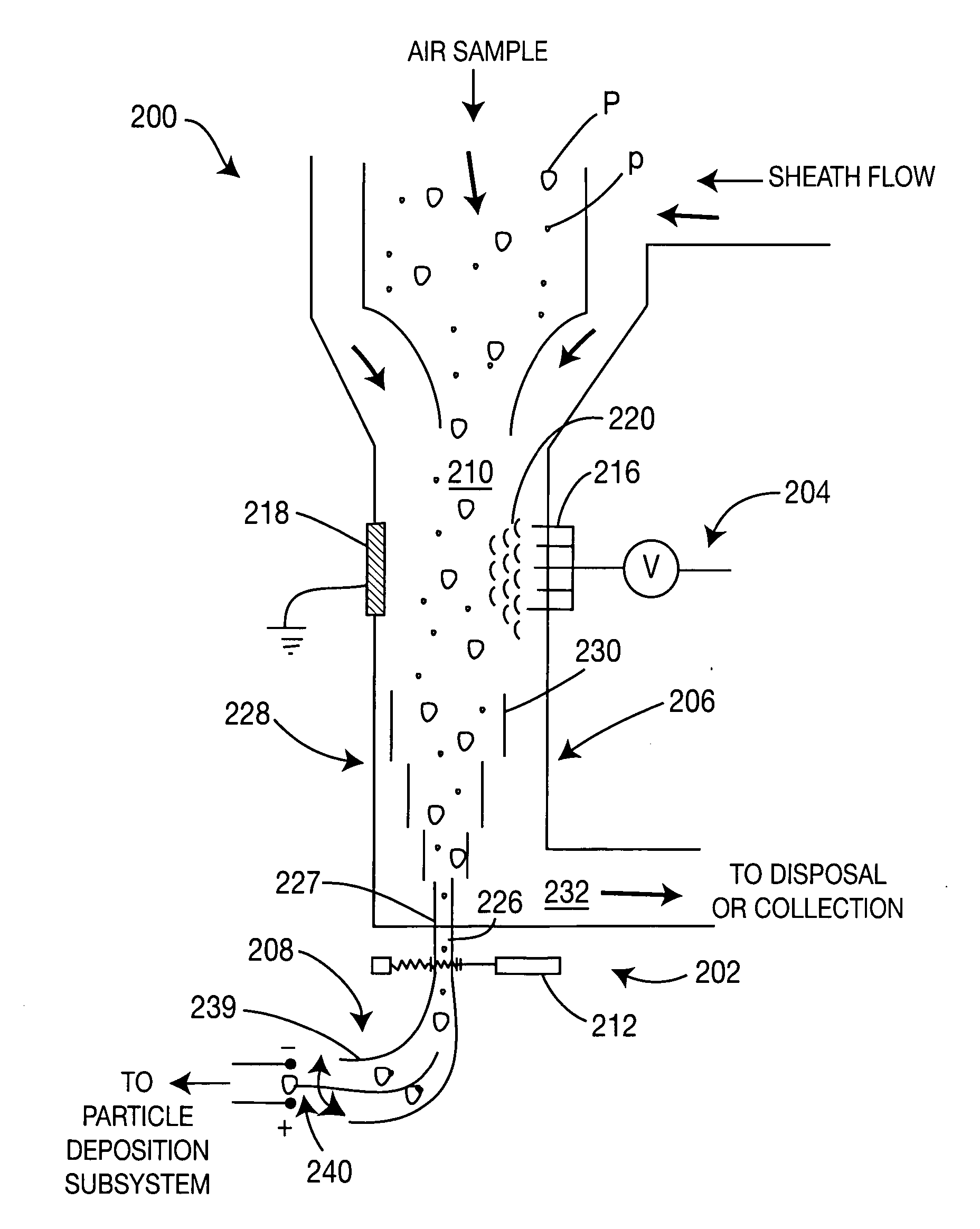
[0039]FIG. 2 is a schematic diagram illustrating a particle sorting system 200 according to the present invention. In one embodiment, the system 200 is substantially similar to the particle sorting system 100 illustrated in FIG. 1 and comprises four main components: a spectrographic identification subsystem 202, a particle charging section 204, a particle focusing section 206 and a particle deposition subsystem 208. However, the four main components of the system 200 are configured in a slightly different manner with respect to the configuration of the particle sorting system 100.

[0040] In one embodiment, the particle charging section 204 comprises a flow shaft 210 that is adapted to receive an incoming air sample (containing one or more different types of particles). In addition the flow shaft 210 is adapted to receive a sheath flow that combines with the incoming air sample to form a combined stream for better transporting particles contained within the air sample to other compone...

third embodiment

[0052]FIG. 5 is a schematic diagram illustrating a particle sorting system 500 according to the present invention. In one embodiment, the particle sorting system 500 comprises four main components: a spectrographic identification subsystem 502, a particle charging section 504, a particle focusing section 506 and a particle deposition subsystem 508. However, these four main components of the system 500 are configured in a manner that is different with respect to the configuration of the components of the particle sorting systems 100 and 200 discussed above.

[0053] In one embodiment, the particle charging section 504 comprises an air sample shaft 540 and an array of electrodes 516. The air sample shaft 540 is adapted to deliver an air sample to the particle sorting system 500 (e.g., from a virtual impactor or other sample collection means), and includes a first end 542 that opens into a larger flow shaft 510 or deposition chamber, where the air sample combines with a sheath flow to for...


PUM

PropertyMeasurementUnit
diameteraaaaaaaaaa
velocityaaaaaaaaaa
electrostatic chargeaaaaaaaaaa

Abstract

An apparatus for airborne particle sorting is provided comprising a charging system adapted for applying an electrostatic charge to the particles, such that particles of at least a first group are deflected to a greater extent than particles of a second group are deflected. A focusing system is adapted for electrostatically focusing substantially at least the particles of the first group into a focused stream that is narrower than the input air stream. A deposition system is adapted for substantially depositing the particles of the first group from the focused stream upon a target surface, where the target surface may be transported to an analysis system capable of analyzing the particles deposited thereon.

Description

CROSS REFERENCE TO RELATED APPLICATIONS [0001] This application claims the priority of U.S. Provisional Patent Application No. 60 / 504,682, filed Sep. 19, 2003 (entitled “Electrostatically Enhanced Particle Sorting and Deposition”), which is herein incorporated by reference.FIELD OF THE INVENTION [0002] The present invention generally relates to the sampling of air, and more particularly relates to the collection and sorting of aerosol particles from air samples. BACKGROUND OF THE INVENTION [0003] There is an increasing demand for air sampling systems for military, private or individual use that are capable of sorting particles of interest (e.g., aerosol particles) from an incoming air sample. Sorting of particles enables a more rapid and accurate analysis of the contents of an air sample by reducing the amount of negligible particles in the sample prior to performing analysis techniques (e.g., such as spectrographic discrimination). Particles of interest are typically separated from...

Claims


Application Information

Patent Timeline
Patent Type & Authority Applications(United States)
IPC IPC(8): B03C3/36G01N15/14
CPCB03C3/36G01N15/1404G01N15/1459Y10T436/117497Y10T436/25375Y10T436/25Y10T436/25875G01N2015/149G01N15/149
Inventor PLETCHER, TIMOTHY ALLENCOYLE, PETER JAMESMCGINN, JOSEPH THOMASKELLER, DAVID
Owner SARNOFF CORP
Learn More