
Arrangement and a method relating to phase locking

a phase locking and arrangement technology, applied in the direction of electrical equipment, pulse automatic control, etc., can solve the problems of complex methods for driving the vco to the appropriate frequency at phase locking, lack of frequency lock functionality, and high noise level

Inactive Publication Date: 2005-05-19
HIGHBRIDGE PRINCIPAL STRATEGIES LLC AS COLLATERAL AGENT
View PDF5 Cites 5 Cited by
  • Summary
  • Abstract
  • Description
  • Claims
  • Application Information

AI Technical Summary

Benefits of technology

[0021] It is an advantage of the invention that phase lock to a selected frequency or to a selected frequency harmonic can be achieved particularly in a few microseconds time, most particularly within approximately two μs.
that phase lock to a selected frequency or to a selected frequency harmonic can be achieved particularly in a few microseconds time, most particularly within approximately two μs.

Problems solved by technology

However, a disadvantage of such digital circuits is that the noise level is high, particularly a considerable noise of the phase of the phase locked VCO signal will result.
It is however a drawback of such circuits that they do not contain any frequency lock functionality.
Today known methods for driving the VCO to the appropriate frequency at phase locking are complicated and the time it takes to acquire phase lock is comparatively long.
Even if the noise will be lower using such a method, it still takes a long time to perform a frequency shift.
However, this device is complicated and requires complicated control means.

Method used


Image

  • Arrangement and a method relating to phase locking
  • Arrangement and a method relating to phase locking
  • Arrangement and a method relating to phase locking

Examples


Embodiment Construction

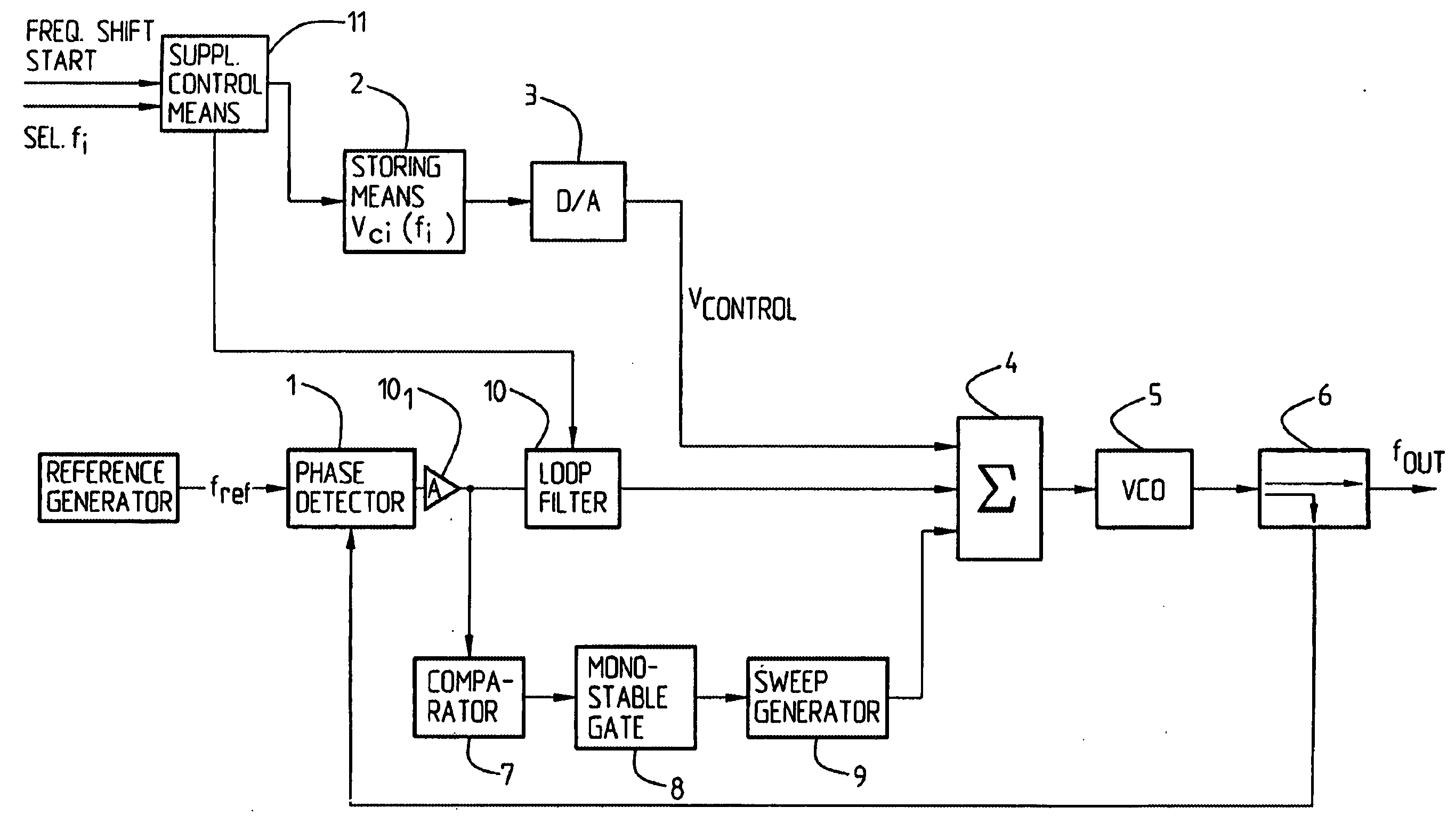
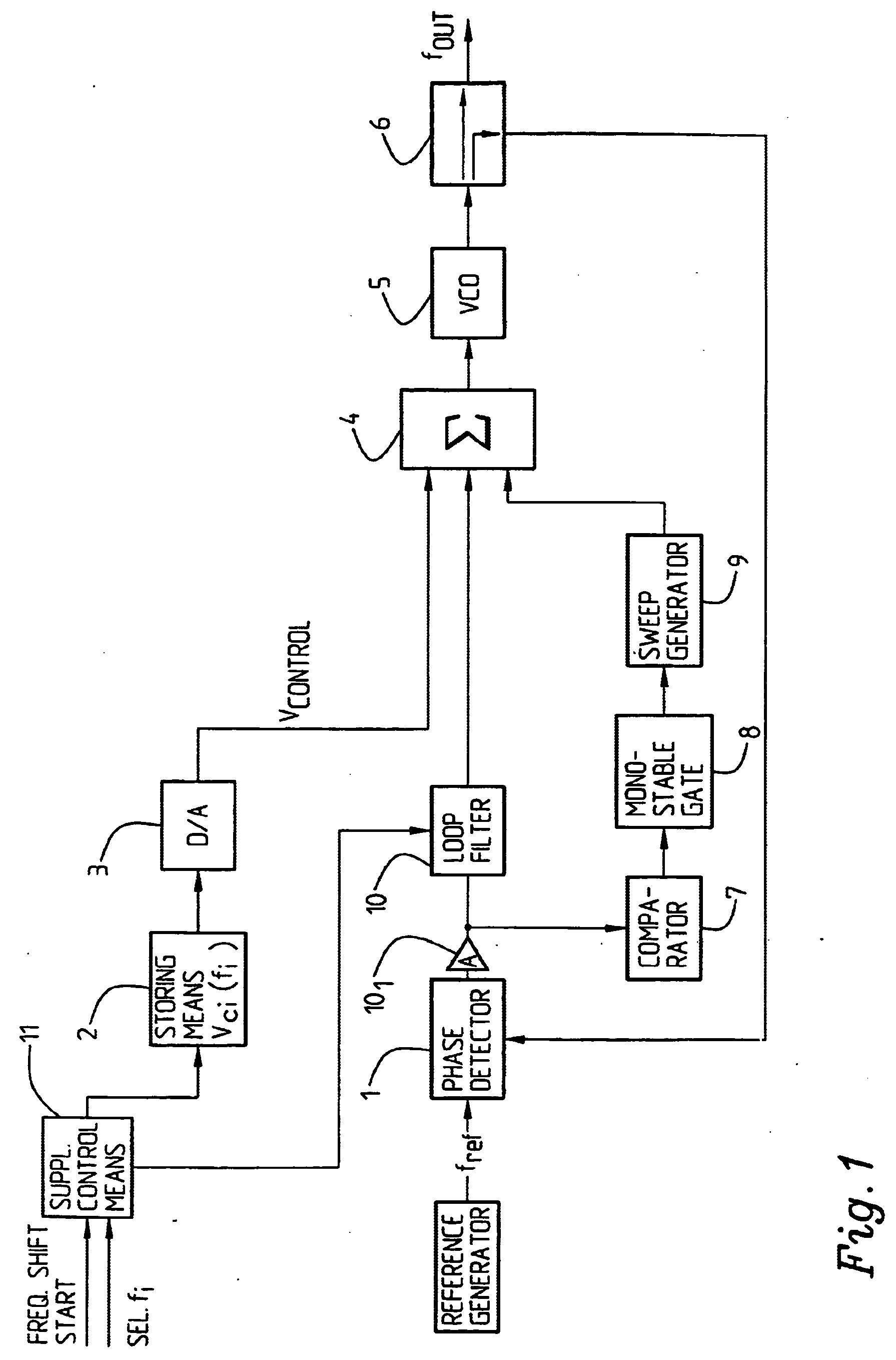
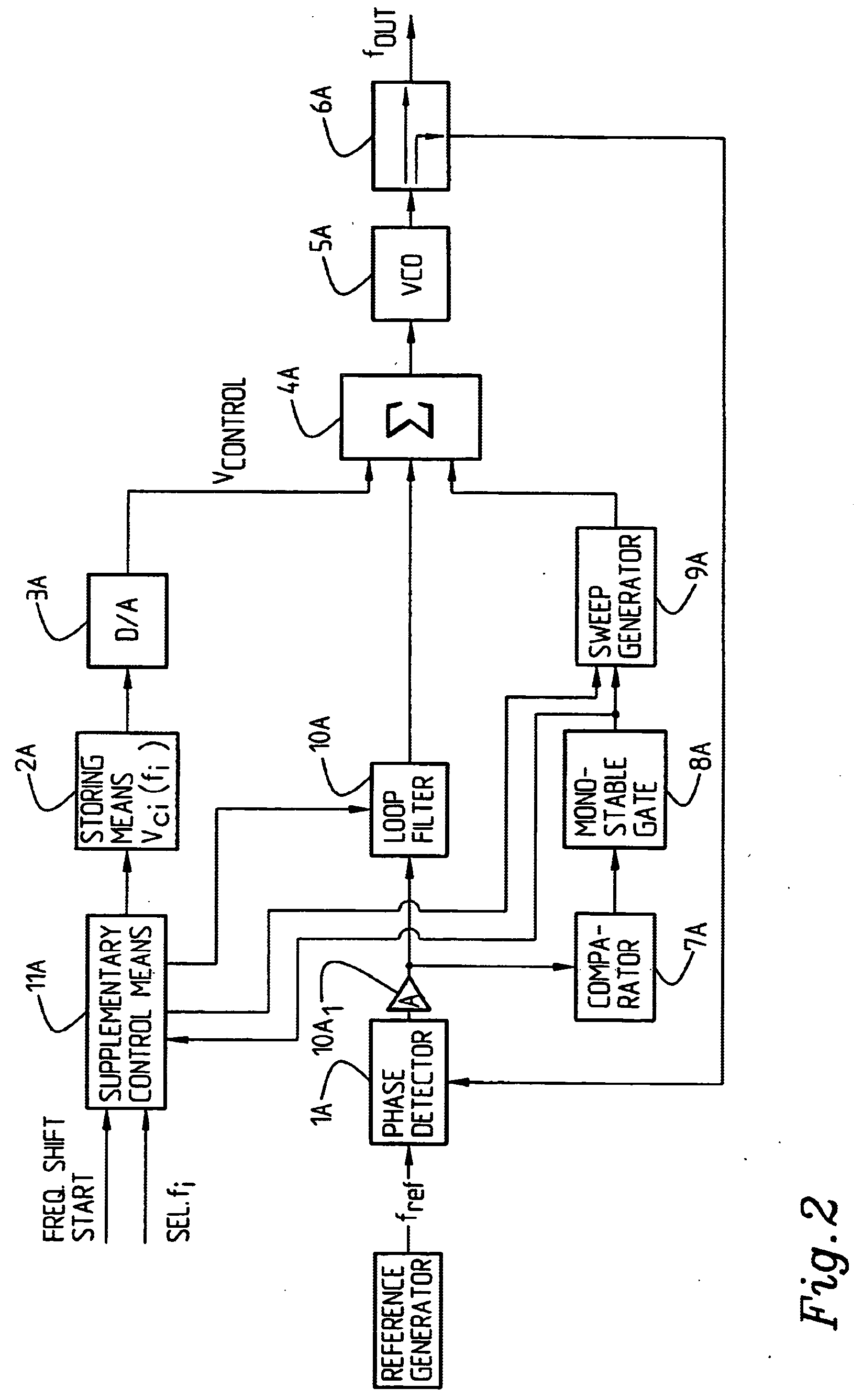
[0031] According to the invention a reference frequency fref is input to a phase detector 1 to lock VCO 5 in a phase loop to a selected harmonic of the reference frequency. In general terms, the VCO 5 is first driven, coarsely, using a first (coarse) control voltage Vcontrol, to a frequency which is somewhat lower (here; it could alternatively have been higher then instead sweeping downwards) than the selected or desired frequency, particularly frequency harmonic of a reference frequency. A voltage sweep is then added by sweep generator 8 to the first control voltage. This will drive the VCO frequency towards the selected frequency harmonic. The frequency difference between the selected or desired frequency harmonic and the VCO frequency output is detected as Δfc, i.e. the error frequency, by the comparator 7 used to provide distinct “switches”, and a retriggerable mono-stable gate 8 is used to provide sufficiently long and reproducible pulses. The Δfc value is used to control the s...


PUM


Abstract

The present invention relates to an arrangement for phase locking of a Voltage Controlled Oscillator (VCO) to a selected frequency harmonic among a number of predetermined or available frequencies (harmonics), comprising a reference generator for generating a reference frequency, a phase lock loop (1; 101; 10, 4, 5, 6, 9) for producing an output signal in response to the input reference frequency, said phase lock loop comprising (enclosing) a phase detector (1), a loop filter (10), said VCO (5), adding means (4) and a power splitter (6). The arrangement also includes a sweep generator (9). It further comprises or is associated with storing means 82) for storing information about, for each selectable or available frequency harmonic, a first (coarse) control voltage providing a VCO frequency output which is lower / higher than, and differs from the selected frequency (harmonic) by a given value (Δf1). That the sweep generator (9) adds (superimposes) a controllable sweep voltage to / on the first control voltage at least until a varying, second frequency difference (Δfc) between the output VCO frequency and the selected frequency harmonic reaches a given value. Monitoring / detecting means are provided for detecting the varying, second frequency difference (Δfc) between the selected frequency harmonic and the VCO output frequency, and sweep generator control means are provided for reducing the sweep rate until the VCO is phase locked to the selected frequency harmonic.

Description

FIELD OF THE INVENTION [0001] The present invention relates to an arrangement for phase locking of a Voltage Controlled Oscillator (VCO) to a selected frequency harmonic of a number of predetermined, i.e. available, frequency harmonics of a reference frequency, comprising a reference generator for generating said reference frequency, a phase lock loop for producing an output signal in response to the input reference frequency, which phase lock loop comprises a phase detector, said VCO, a filter and a sweep generator. The invention also relates to a method for locking the phase of a Voltage Controlled Oscillator to a selected frequency harmonic of a number of available or predetermined frequency harmonics of an input reference frequency. The invention also relates to an arrangement and a method through which a frequency shift can be provided for. STATE OF THE ART [0002] Pre-manufactured digital PLL (Phase Lock Loop) circuits are available which comprise a frequency as well as a phase...

Claims


Application Information

Patent Timeline
IPC IPC(8): H03L7/00H03L7/091H03L7/107H03L7/12H03L7/20
CPCH03L7/091H03L7/20H03L7/12H03L7/107H03L7/1075
Inventor HYDEN, LENNARTLOFTER, BJORNCEDERLOF, MANS
Owner HIGHBRIDGE PRINCIPAL STRATEGIES LLC AS COLLATERAL AGENT
Learn More