
Paintball munition chamber and paintball gun utilizing the same

a paintball gun and paintball technology, applied in the field of paintball guns, can solve the problems of increasing the likelihood of damage to paintballs, affecting the accuracy of paintballs, and complex than gravity feed hoppers

Inactive Publication Date: 2005-05-19
WATSON JASON D +1
View PDF47 Cites 5 Cited by
  • Summary
  • Abstract
  • Description
  • Claims
  • Application Information

AI Technical Summary

Benefits of technology

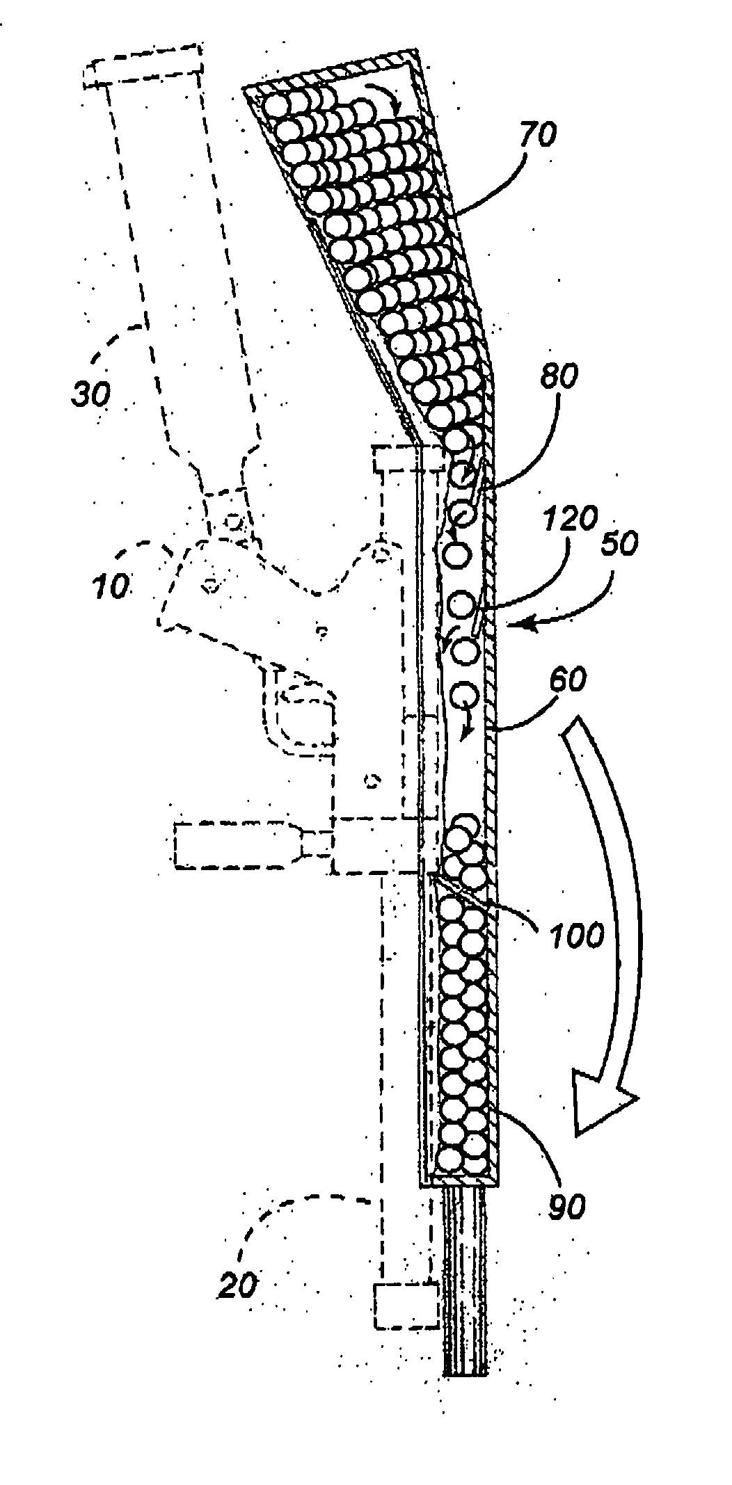
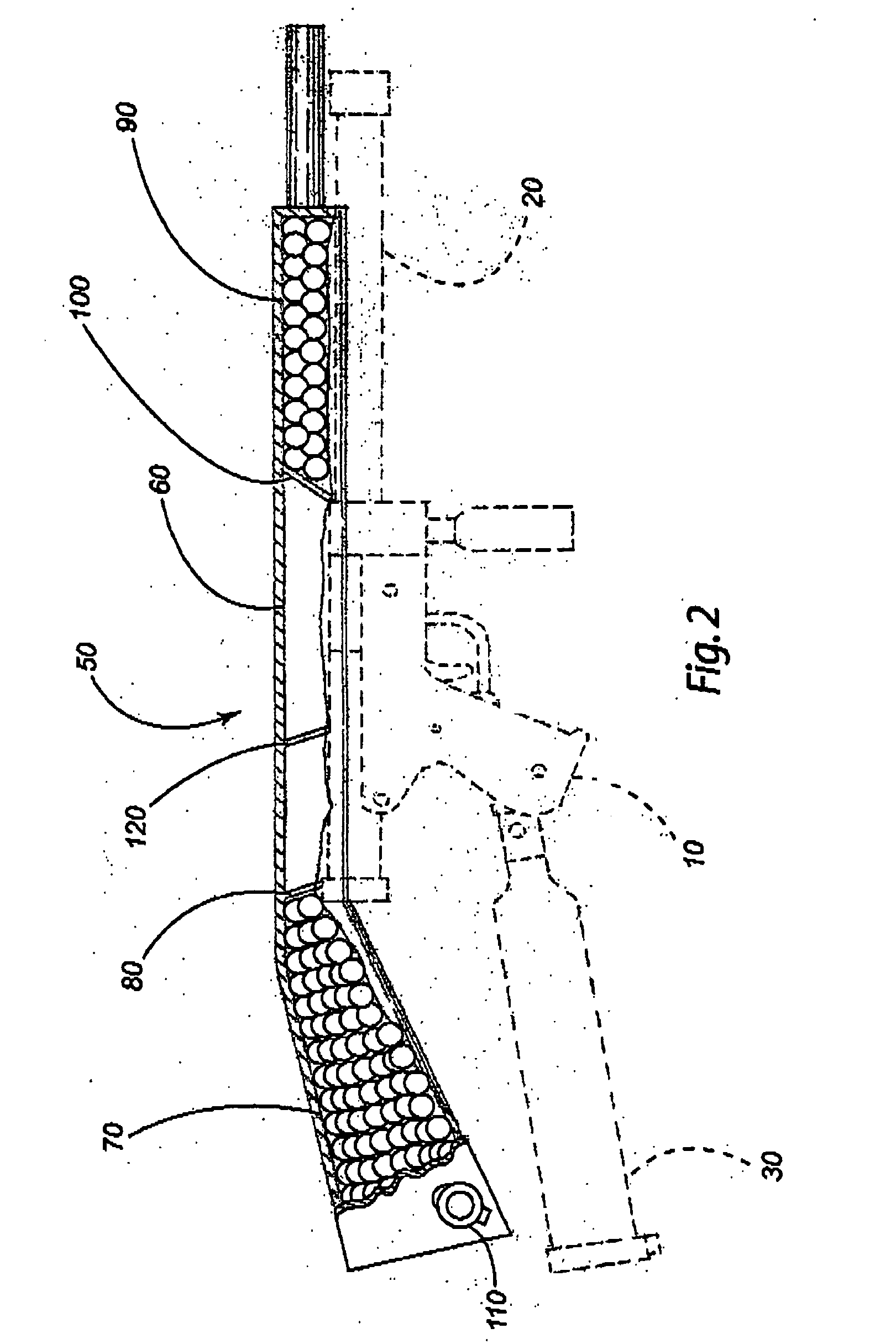
[0010] The present invention is an improved hopper for holding paintballs and feeding them to a paintball gun. The hopper is in communication with the chute leading into the breech of a typical paintball gun and more closely fits to the shape of the rest of the gun than typical paintball hoppers and may be shaped in such a manner as to simulate the overall look of an actual gun. A smaller portion of the hopper is above the breech and runs from a short distance in front of the breech to a point above and just to the rear of the handle and trigger where most paintball guns terminate. From this point another, larger portion of the hopper extends back and slightly downward from the rear of the gun. This section may be shaped to generally imitate the shoulder stock on a real gun. A one way gate operates between these two sections of the hopper and allows paintballs to flow from the larger, rear section to the smaller, forward section and prevents their return to the rear. The hopper is filled through a port in the rear section.

Problems solved by technology

The single file spiral prevents jams which can interrupt the flow of paintballs and put a player at a disadvantage until the proper flow is re-established.
Harvey provides one solution that is adaptable to current paintball gun models, but it is also more complex than the gravity feed hoppers, and uses mechanical manipulation of the paintballs to feed the gun.
This may increase the likelihood of damaging the paintballs.
In both cases the magazine has a limited capacity and the spring introduces undesirable stress on the paintballs.

Method used


Image

  • Paintball munition chamber and paintball gun utilizing the same
  • Paintball munition chamber and paintball gun utilizing the same
  • Paintball munition chamber and paintball gun utilizing the same

Examples


Embodiment Construction

[0028] The following discussion illustrates only some of the possible configurations claimed in this invention and should not be interpreted as limiting the scope of the claims.

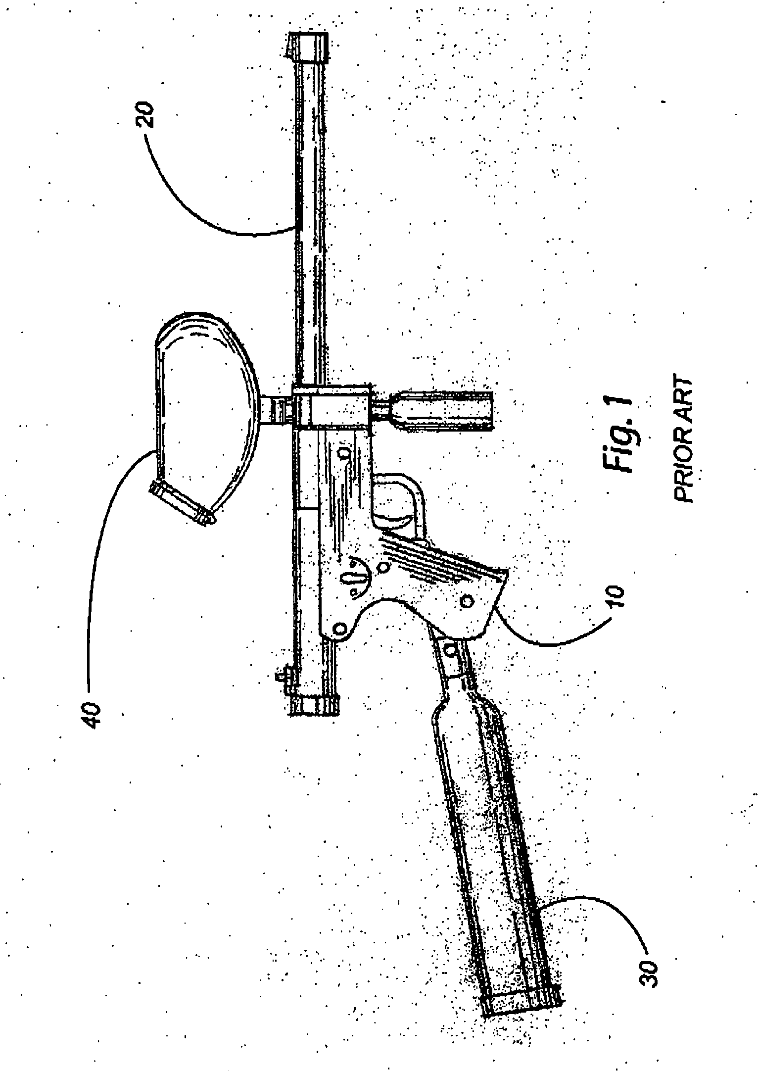
[0029] The present invention is a new hopper configuration for paintball guns. FIG. 1 shows a side view of a prior art paintball gun which has the following: a working section (10) containing the mechanical workings of a paintball gun such as the trigger, the bolt, and valves; a barrel (20) through which the paintballs are propelled; a gas cylinder (30) which supplies pressurized gas to power the gun; and a hopper (40) which stores a quantity of paintballs which are gravity fed into the working section (10) of the paintball gun.

[0030]FIG. 2 shows the hopper (50) of the preferred embodiment of the current invention placed on the prior art paintball gun shown in FIG. 1. In general, the hopper (50) is shaped to provide the overall look of a real gun. Within the hopper (50) is a central chamber (60) located abo...


PUM


Abstract

A hopper for a paintball gun is disclosed. The hopper is a gravity feed hopper and has a lower profile than those in the previous art. The hopper fits closely to the profile of the paintball gun and may have multiple chambers along with unidirectional gates to control the flow between chambers and within chambers as well. This invention may take the form of a hopper mounted onto a previous type of paintball gun as an aftermarket add-on or it may be built into the paintball gun itself as part of its construction.

Description

FIELD OF THE INVENTION [0001] This invention relates generally to paintball guns. More specifically, the invention relates to a method and apparatus for a hopper holding the paintballs to be fired from a paintball gun. The current invention is a lower profile hopper essentially fitting into the form of the gun and may be either a retrofit to current paintball gun designs, or it may be integrated into the gun at the time of manufacture. BACKGROUND OF THE INVENTION [0002] Paintball sporting has grown in popularity as a form of recreation over the last 20 years. The game is a form of simulated combat and typically uses gas powered guns which are capable of propelling marker dye filled gelatinous balls approximately 0.68″ in diameter at speeds around 290 feet per second. These paintballs rupture when striking an object, leaving the object marked by the dye contents. The paintballs are fired at opponents, and any person hit by a paintball that ruptures will experience an identifiable mar...

Claims


Application Information

Patent Timeline
Patent Type & Authority Applications(United States)
IPC IPC(8): F41B11/02
CPCF41B11/52
Inventor WATSON, JASON D.SMITH, JOHN L.
Owner WATSON JASON D
Learn More