
Indicator system for vehicles

a technology for indicators and vehicles, applied in the direction of identification means, instruments, transportation and packaging, etc., can solve the problems of easy collisions, disharmonic comparison, and inability of drivers therein to see the blinking indicators of braking vehicles in front,

Inactive Publication Date: 2005-05-12
EXON SCIENCE INC
View PDF7 Cites 33 Cited by
  • Summary
  • Abstract
  • Description
  • Claims
  • Application Information

AI Technical Summary

Benefits of technology

[0015] A main object of the present invention is to provide an indicator system which can present various dynamic indicating signals or signs at a conspicuous position especially for warning or reminding vehicles following behind.
[0016] A second object of the present invention is to provide a dynamic indicator display at a third indicator position higher than the traditional first and second indicator positions at the opposite sides of the bottom of a vehicle's rear portion.
[0017] A third object of the present invention is to provide a multi-functional indicator display at a third indicator position higher than the traditional first and second indicator positions at the opposite sides of the bottom of a vehicle's rear portion.
[0018] A fourth object of the present invention is to provide a dynamic indicator display with multi-functions at a third indicator position higher than the traditional first and second indicator positions at the opposite sides of the bottom of a vehicle's rear portion.

Problems solved by technology

However, if the vehicles behind are those whose front portions are very high or big, then the drivers therein can hardly or inconveniently see the blinking indicators of a braking vehicle in front of them since the first and second set indicators are commonly positioned at the below sections of the rear portion of a vehicle.
This is very dangerous and it's easy to cause collisions accordingly.
It's static and humdrum thereby becoming a disharmonic comparison to the vivid world around.
Furthermore, It only lightened when the vehicles is in braking.
Moreover, the illumination changing modes of the LEDs are arranged according to the amount of pressure applied to the brake pedal, such that its application is relatively limited then.
Similar problems haven't been solved when a front car is tuning or is backing.
It is still inconvenient for drivers of those following vehicles whose front portions are high or big to see the first and second indicators which indicate the turning or backing status thereof.

Method used


Image

  • Indicator system for vehicles
  • Indicator system for vehicles
  • Indicator system for vehicles

Examples


Embodiment Construction

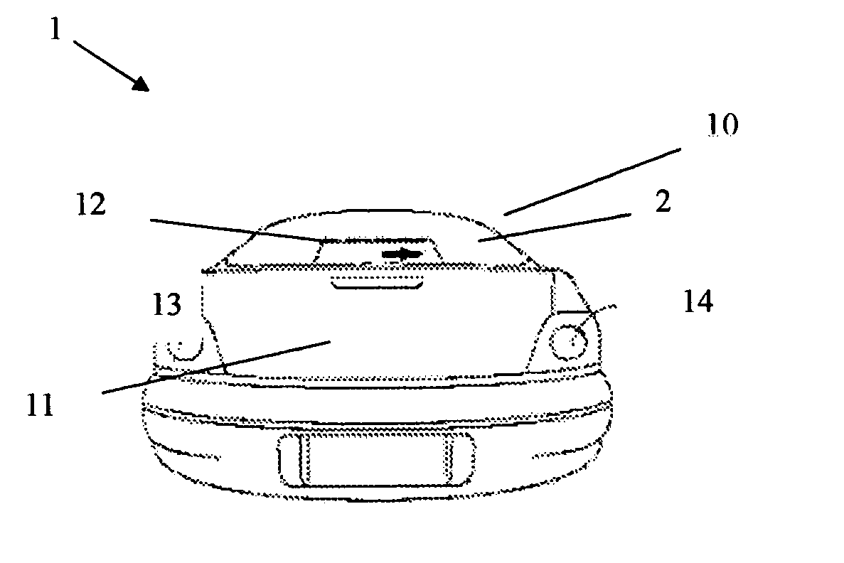
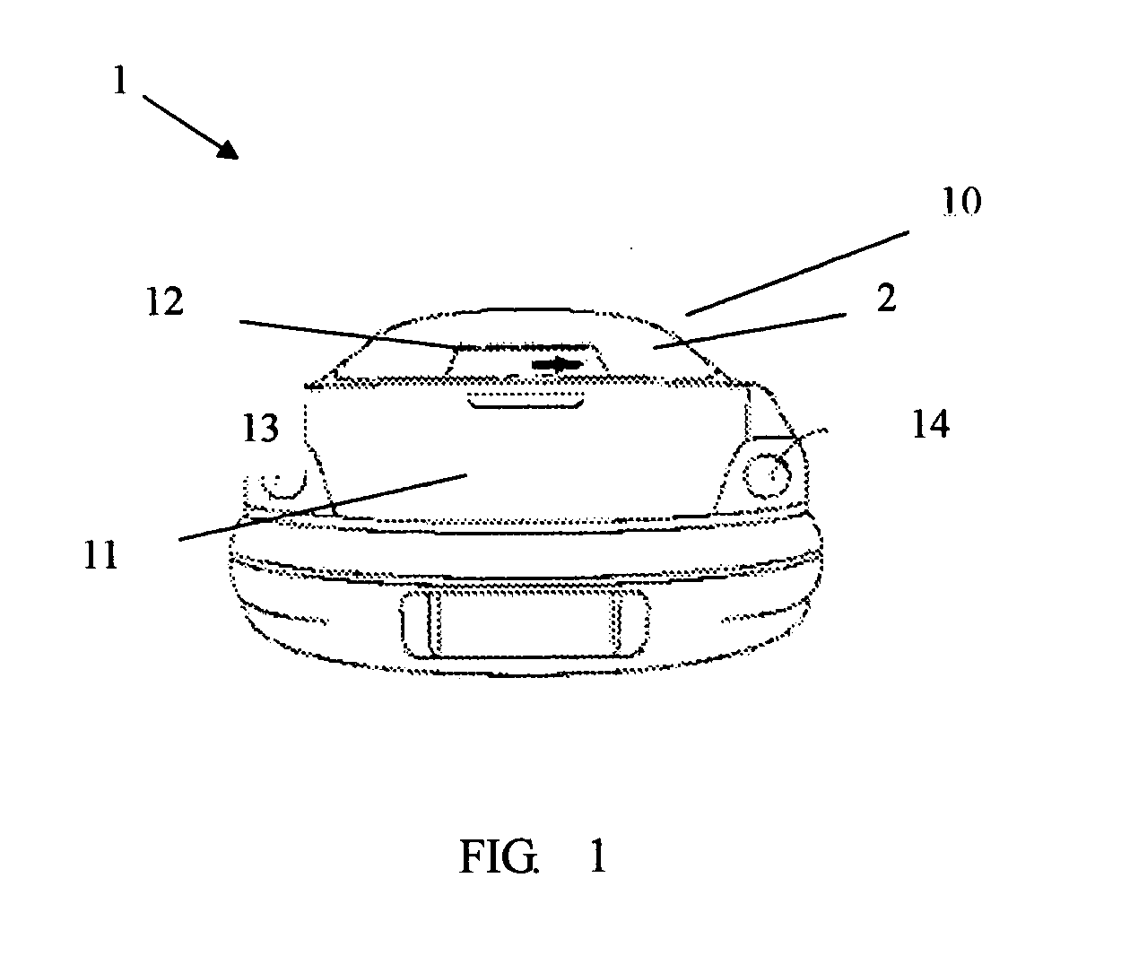
[0033] Referring to FIG. 1, the present invention provides an indicator system (not labeled) for a vehicle 1. The vehicle 1 has a body 11, a roof 10 and a rear window 12 between the roof 10 and the rear portion of the body 11. Two sets of traditional turn indicators 13 and 14 are positioned at opposite sides of the rear portion of the body 11 and approach the bottom edge of the rear portion in a conventional way.

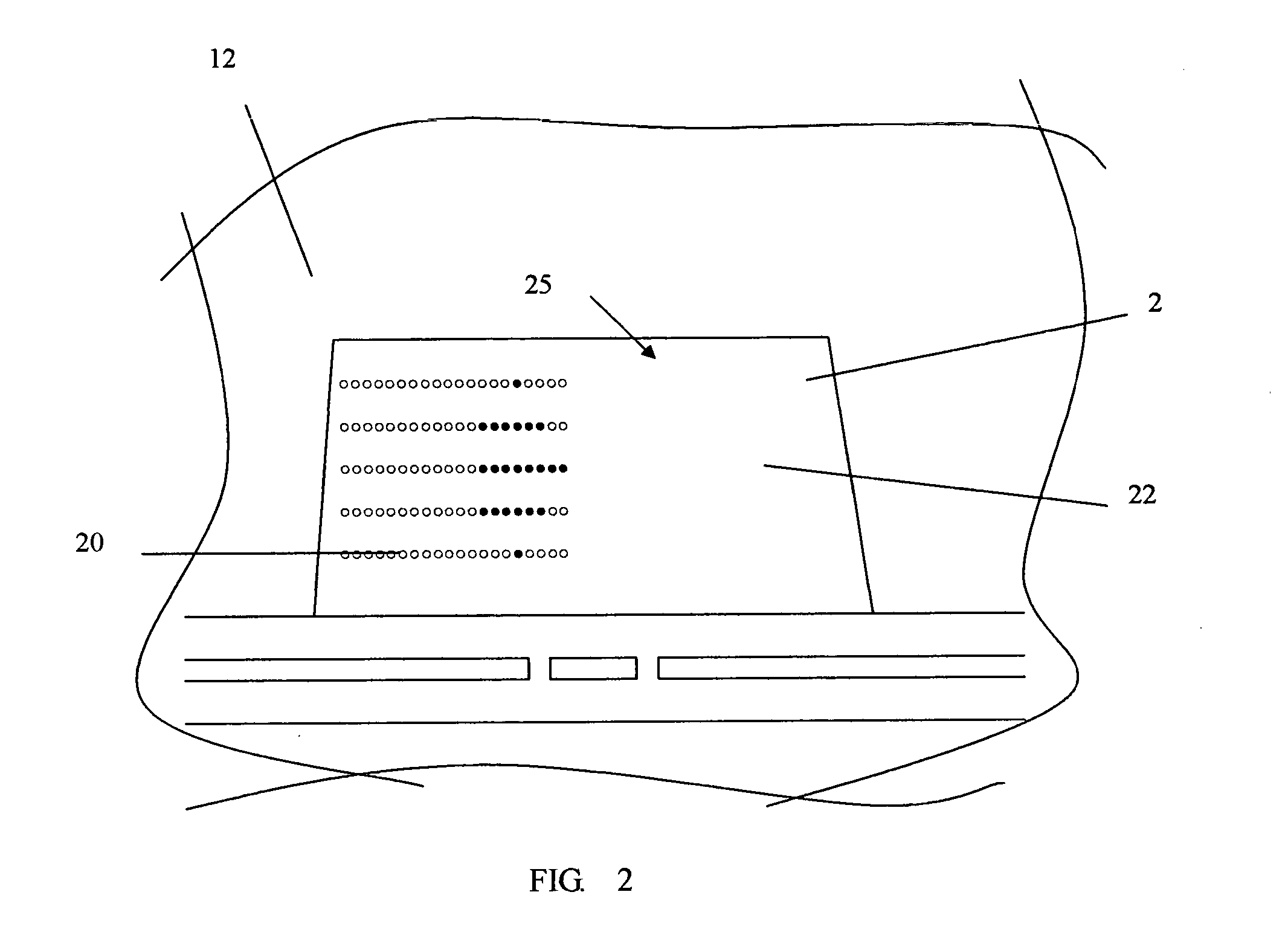
[0034] The indicator system in accordance with the present invention is in communication with a control system (not shown) installed within the vehicle and comprises an indicator display 2. The indicator display 2 is located at a position a certain distance higher than the bottom edge of the rear portion, actually higher than the positions of the traditional turn indicators 13 and 14. Hence, the indicator display 2 of the present invention is located in a conspicuous position so that it is very easy and convenient to see even for drivers sitting in those vehicles whose fron...


PUM


Abstract

An indicator system for a vehicle is in communication with a control system installed within the vehicle and comprises an indicator display. The indicator display is located at a position a certain distance higher than the bottom edge of the vehicle's rear portion and includes a plurality of LEDs which can present different dynamic patterns indicating different status of the vehicle according to different types of instructions by the control system.

Description

TECHNICAL FIELD [0001] The present invention relates to an indicator system for vehicles, more particularly to a vehicular indicator system which can present various dynamic indicating signs or signs at a conspicuous position especially for warning or reminding vehicles following behind. DESCRIPTION OF RELATED ARTS [0002] A normal indicator system for vehicles usually comprises two sets of indicators positioned apart at the opposite sides of a vehicle's back portion, which are commonly called as first and second set indicators. [0003] The first and second set indicators of the indicator system are commonly used to indicate the turning status of the vehicle, or to warn when the vehicle is braking, backing or breaking down, so that the drivers of vehicles behind may adjust their vehicular speeds or adopt other proper measures accordingly. The first and second indicator system is normally controlled by a controlling system of the vehicle. [0004] One type of said controlling system for ...

Claims


Application Information

Patent Timeline
IPC IPC(8): B60Q1/22B60Q1/30B60Q1/34B60Q1/44B60Q1/50
CPCB60Q1/22B60Q1/302B60Q1/503B60Q1/44B60Q1/34B60Q1/50B60Q1/5035
Inventor SU, WEN-WEI
Owner EXON SCIENCE INC
Learn More