
Moving a virtual articulated object in a virtual environment while avoiding internal collisions between the articulated elements of the articulated object

Active Publication Date: 2005-05-05
SN DETUDE & DE CONSTR DE MOTEURS DAVIATION S N E C M A
View PDF6 Cites 3 Cited by
  • Summary
  • Abstract
  • Description
  • Claims
  • Application Information

AI Technical Summary

Benefits of technology

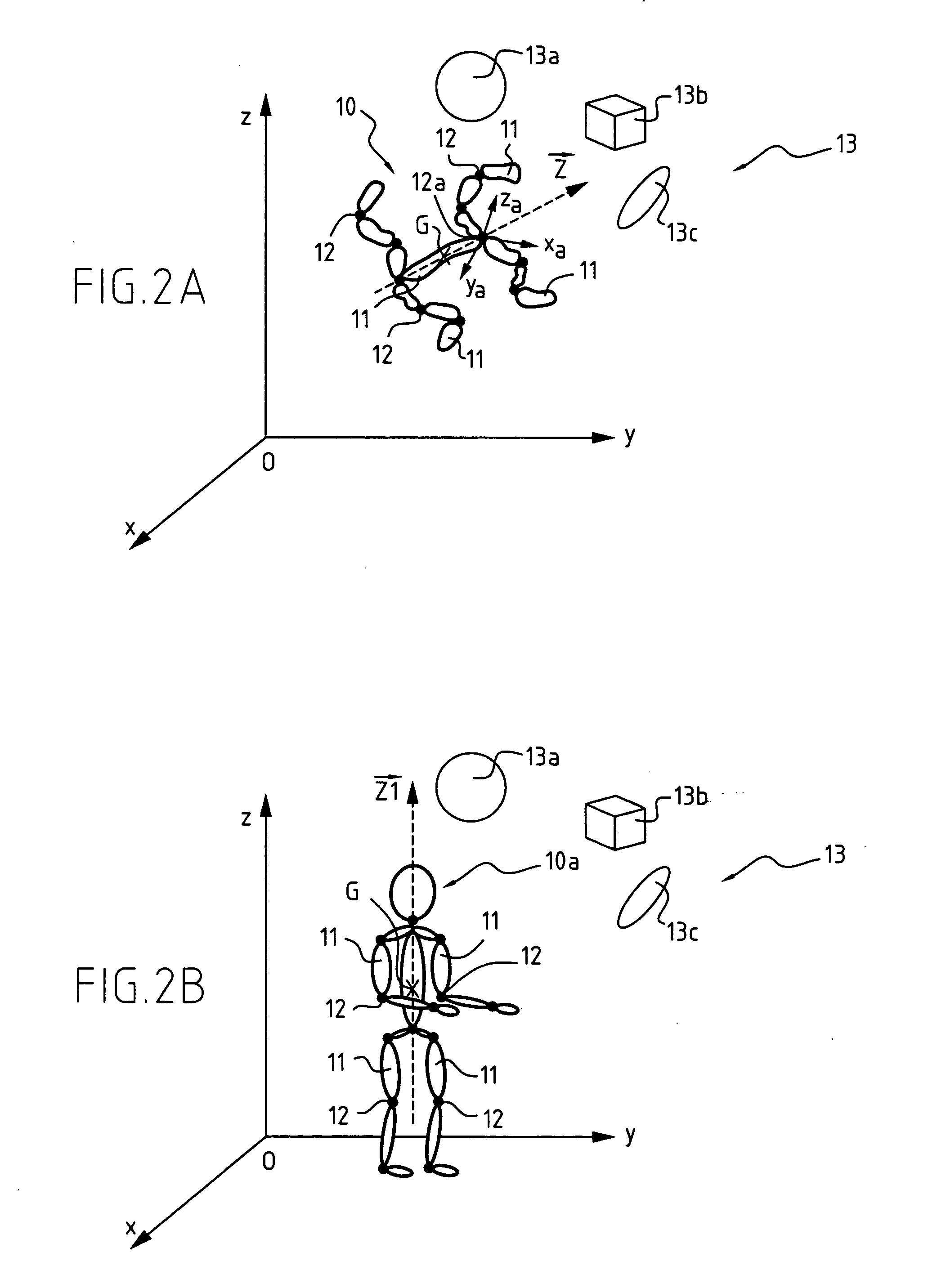
[0013] Another object is to avoid internal collisions between all of the articulated elements of the articulated object by causing the various articulated elements to avoid one another.
[0018] moving the given articulated element away from the other articulated elements of the articulated object in a movement defined as a function of the single extraction vector by acting on the degrees of freedom of the articulated object in order to avoid a collision between the given articulated element and the other elements of the articulated object.
[0019] Thus, the method of the invention avoids collision between a given articulated element of the articulated object and the other articulated elements of the articulated object by using a single calculation of an interaction distance.
[0020] This makes it possible to model the movement of the articulated object with great accuracy and with optimized calculation time.
[0024] In a first embodiment of the invention, the interaction distance corresponds to a penetration depth, such that the extraction vector is equal to the coordinates of the second point minus the coordinates of the first point, the penetration depth enabling the articulated object to move with a limited and controlled amount of collision between its articulated elements.

Problems solved by technology

However, the posture of the dummy, as it moves, can be arbitrary and that can lead to a collision between a given member of the dummy and the other members of the dummy.
That reduces the accuracy with which movement of the dummy is modeled.

Method used


Image

  • Moving a virtual articulated object in a virtual environment while avoiding internal collisions between the articulated elements of the articulated object
  • Moving a virtual articulated object in a virtual environment while avoiding internal collisions between the articulated elements of the articulated object
  • Moving a virtual articulated object in a virtual environment while avoiding internal collisions between the articulated elements of the articulated object

Examples


Embodiment Construction

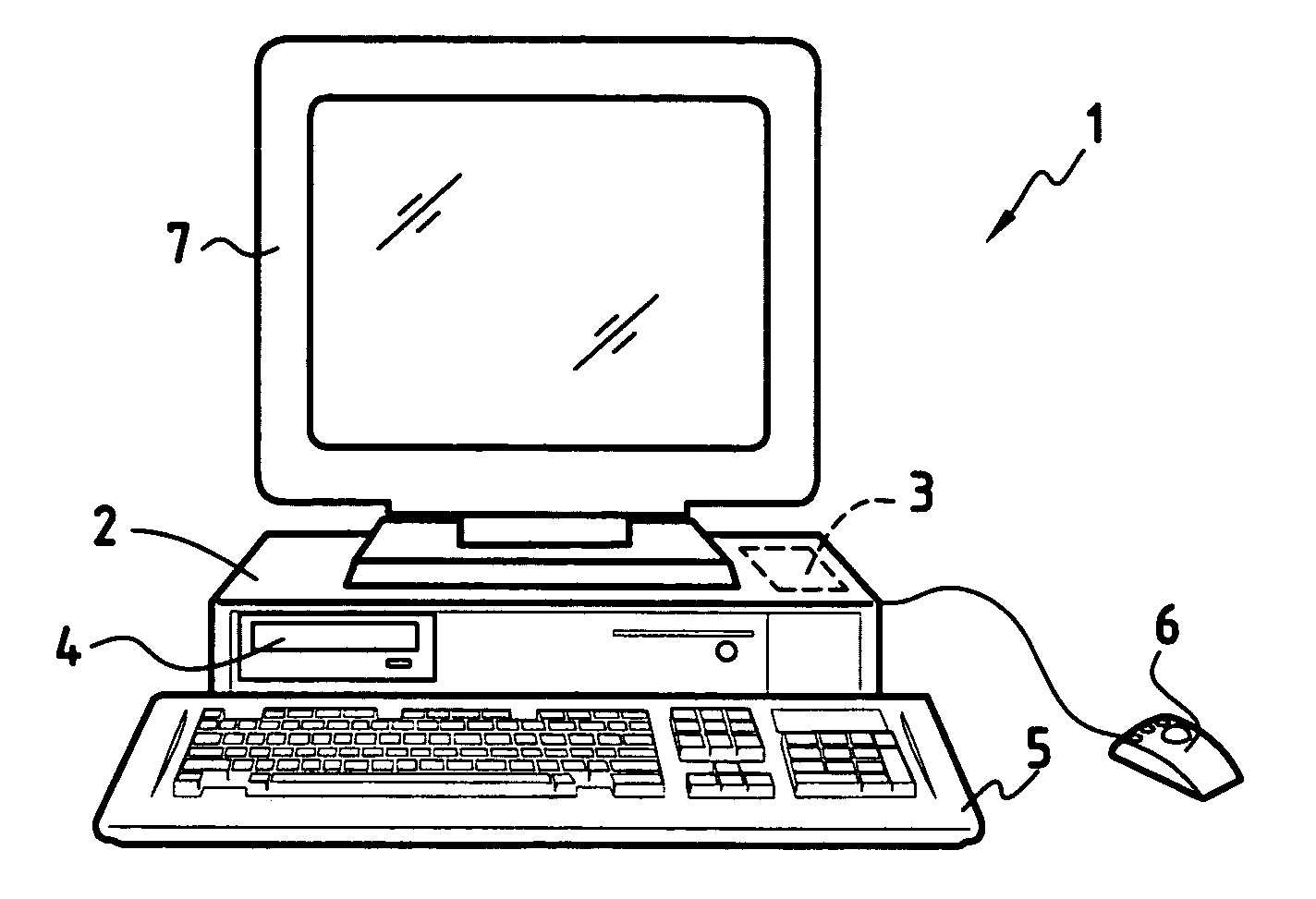
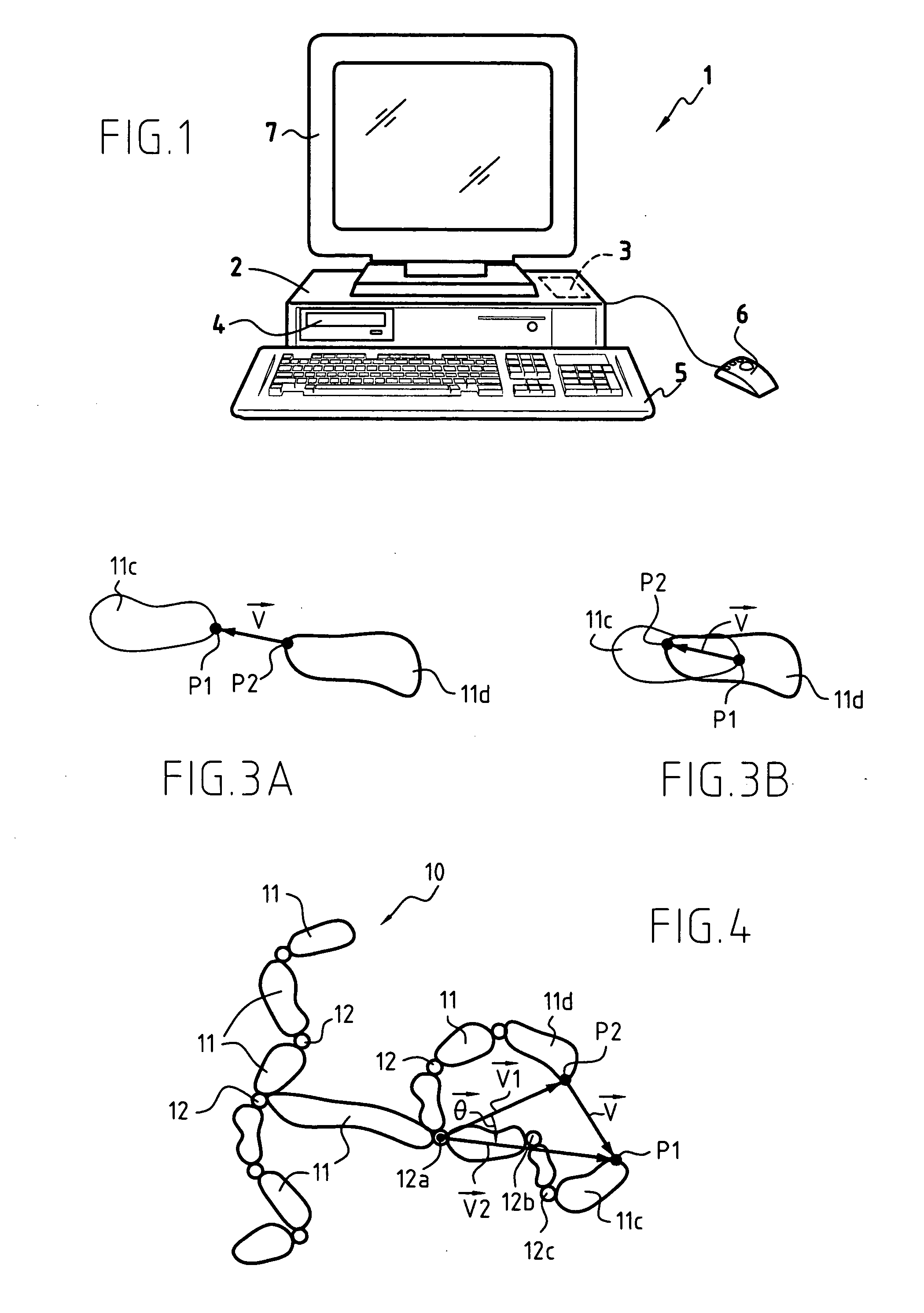
[0051]FIG. 1 shows a system which can be used for modeling the movement of an articulated object. The system comprises a workstation or computer 1 having good graphics capacity, used for executing a computer program designed to implement the method of the invention.

[0052] The computer 1 comprises the hardware means that are usually found in this type of apparatus. More particularly, the computer comprises a central unit 2 which executes the sequences of instructions in the program for implementing the method of the invention, a central memory 3 which stores the data and the programs that are being executed, digital data storage media (hard disk, CD 4, floppy disk, . . . ) for long-term storage of the data and the programs used, input peripherals (keyboard 5, 2D or 3D mouse 6, joystick, . . . ) and output peripherals (screen 7, stereoscopic headsets or glasses, . . . ) in order to be able to view the movement of an articulated object.

[0053] Naturally, in order to increase calculati...


PUM


Abstract

A method of moving a virtual articulated object in a virtual environment in a succession of unit movements, the articulated object comprising a set of articulated elements connected together by a set of joints, the relative positions of the articulated elements being defined by a plurality of joint angles about a plurality of degrees of freedom, the method comprising the following steps: calculating an interaction distance between a given articulated element and the other articulated elements of the articulated object; extracting from said interaction distance, a first point belonging to the given articulated element, and a second point belonging to one of the other articulated elements of the articulated object; defining a single extraction vector from said first and second points; and moving the given articulated element away from the other articulated elements of the articulated object in a movement defined as a function of the single extraction vector by acting on the degrees of freedom of the articulated object in order to avoid a collision between the given articulated element and the other elements of the articulated object.

Description

FIELD OF THE INVENTION [0001] The present invention relates to the field of simulating movement of a virtual articulated object in a virtual environment. In particular, the invention relates to avoiding collisions between the articulated elements of the articulated object and the remainder of the articulated object. BACKGROUND OF THE INVENTION [0002] In numerous industries, such as the aviation or space industries, it is common practice to use models in virtual reality. For example, a digital mock-up is often used to evaluate interference between various parts. [0003] Similarly, modeling can be used to simulate human or robot actions in a defined environment in order to visualize the movement that a technician or a robot will need to make in order to undertake those actions, for example. This is useful for validating and optimizing accessibility to certain parts of a machine, such as the parts in an airplane engine, which parts require regular inspection and maintenance. [0004] Thus...

Claims


Application Information

Patent Timeline
IPC IPC(8): B25J9/16G06T13/20G06F17/50
CPCB25J9/1666G05B2219/39096G06T2210/21G06T17/05G06T13/20
Inventor MAILLE, BRUNORAMSTEIN, EDOUARDCHEDMAIL, PATRICK
Owner SN DETUDE & DE CONSTR DE MOTEURS DAVIATION S N E C M A
Learn More