
Efficient model order reduction via multi-point moment matching

a multi-point moment matching and efficient model technology, applied in the field of microelectronic circuit and system design, can solve the problems of inability to adapt smm to parallel, inability to achieve parallel processing, and inability to achieve numerical stability of q order approximation, so as to reduce truncation errors and ensure numerical stability of approximation. , the effect of numerical stability

Inactive Publication Date: 2005-05-05
ISMAIL YEHEA I
View PDF77 Cites 35 Cited by
  • Summary
  • Abstract
  • Description
  • Claims
  • Application Information

AI Technical Summary

Benefits of technology

"The present invention provides a method and apparatus for simulating linear and nonlinear circuits using a multi-point moment matching technique called MMM. This technique reduces the number of moments required to achieve a specific accuracy, resulting in improved computational efficiency and numerical stability. The MMM technique also allows for parallel processing and is suitable for very large scale integration. The invention also includes an interconnect evaluator for simulating interconnects and a nonlinear circuit simulator for evaluating and optimizing circuit designs. Overall, the MMM technique provides a more efficient and accurate way to simulate complex circuits."

Problems solved by technology

AWE has been referred to above as a Single-Moment Matching (SMM) method of circuit approximation because it looks at each node in isolation of other nodes an approach that creates inefficiencies in terms of processing time and numerical accuracy.
Finally, MMM is highly suitable for parallel processing techniques especially for higher order approximations while using SMM requires calculating the moments sequentially and SMM cannot be adapted to parallel processing techniques.
AWE, while fast, does not allow for parallel processing, which is important as the number of circuit inputs increase.

Method used


Image

  • Efficient model order reduction via multi-point moment matching
  • Efficient model order reduction via multi-point moment matching
  • Efficient model order reduction via multi-point moment matching

Examples


Embodiment Construction

General Description

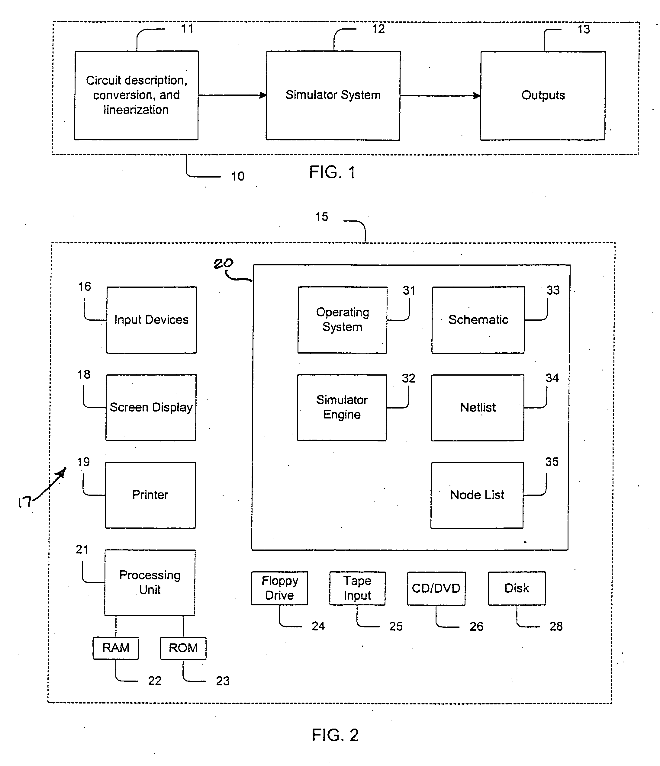
[0068] Referring to the drawings, FIG. 1 is a simplified representation of a circuit simulating system 10 for use in the design and simulation of integrated circuits and / or systems. The circuit simulating system 10 includes a circuit design system 11 and a simulator system 12 which provides outputs, represented by block 13, such as speed of the circuit or system being simulated, power consumption by the circuit or system being simulated, coupling noise, signal skew, for example. The operation of the simulator system 12 is based on model order reduction techniques. In one embodiment, the simulator system 12 is an interconnect evaluator, hereinafter interconnect evaluator 12, which incorporates the multi-point moment matching (MMM) technique / apparatus provided by the present invention. The interconnect evaluator 12 provides verification of the design and operation of circuits or systems being simulated. The interconnect evaluator 12 can be configured to perform DC...


PUM


Abstract

A method for mapping moments in a reduced order system of approximation order q for use in simulating a circuit or system having n state variables at n nodes, the circuit or system having I inputs. The method includes calculating only q+I moments, where q is the approximation order and I is the number of inputs of the circuit or system being simulated, sorting the state variables at the n nodes, selecting q nodes of the n nodes, and calculating the dominate poles and zeros using a multi-point moment matching algorithm to simultaneously match q+I moments at the selected q nodes of the circuit or system. In one embodiment, the method includes using extra dummy inputs such that the total number of inputs equals I, such that K*I>q where K is a constant having a value in the range of about 4 to 8.

Description

CROSS-REFERENCE TO RELATED APPLICATIONS [0001] This application is a division of application Ser. No. 10 / 143,276, filed on May 9, 2002, now U.S. Pat. No. ______, which claims priority of provisional application Ser. No. 60 / 290,465, filed on May 11, 2001.FIELD OF THE INVENTION [0002] This invention relates to the design of microelectronic circuits and systems, and more particularly, to simulators for evaluating the performance of microelectronic circuits and systems prior to fabrication. BACKGROUND OF THE INVENTION [0003] In the process of designing circuits, particularly large scale integrated circuits, it is normal practice to mathematically model the electrical circuits. Many circuit simulators have been developed to mathematically model the circuits. Particularly, the outputs of the circuit are modeled as a function of the inputs to the circuit. The mathematical model is used to determine various response characteristics of the circuit. [0004] Circuit simulation has long been an ...

Claims


Application Information

Patent Timeline
Patent Type & Authority Applications(United States)
IPC IPC(8): G06F17/10G06F17/50
CPCG06F17/504G06F30/3323
Inventor ISMAIL, YEHEA I.
Owner ISMAIL YEHEA I
Learn More