
Sputtering target transport box

Active Publication Date: 2005-05-05
JX NIPPON MINING& METALS CORP
View PDF9 Cites 11 Cited by
  • Summary
  • Abstract
  • Description
  • Claims
  • Application Information

AI Technical Summary

Benefits of technology

[0006] In order to overcome the foregoing problems, an object of the present invention is to provide a sputtering target transport box in which the removal and transport of a sputtering target is easy, and which enables the transport of a sputtering target without causing any damage thereto.
[0007] As a result of intense study to achieve the foregoing object, the present inventors discovered that it is possible to provide a sputtering target transport box in which the removal and transport of a sputtering target is easy, and which enables the transport of a sputtering target without causing any damage thereto by providing supports and a wheel to the bottom plate of the transport box.

Problems solved by technology

Generally, a sputtering target employed in the manufacture of semiconductors and the like is gradually growing in size and becoming heavy, and demands for the flatness and surface cleansibility thereof are becoming increasingly tough.
Further, in addition metal targets, some targets employ brittle materials such as ceramics, and needs are arising for safely transporting such targets from the target manufacturing plant to the workshop for forming thin films via sputtering with such targets.
Since recent-day targets are highly purified, the unit production cost per target is increasing, and it causes the bigger loss in cost if such target is damaged or broken during its transport.
Conventionally, upon simplifying the transport, there were cases where the target would become damaged or broken by colliding during its transport or opening.
Contrarily, when securing the transport in order to prevent the damage or breakage of the target, there are problems such as the opening becomes troublesome, and the transport is hindered due to the increased weight thereof.

Method used


Image

  • Sputtering target transport box
  • Sputtering target transport box
  • Sputtering target transport box

Examples


Embodiment Construction

[0021] The present invention is now explained with reference to the drawings.

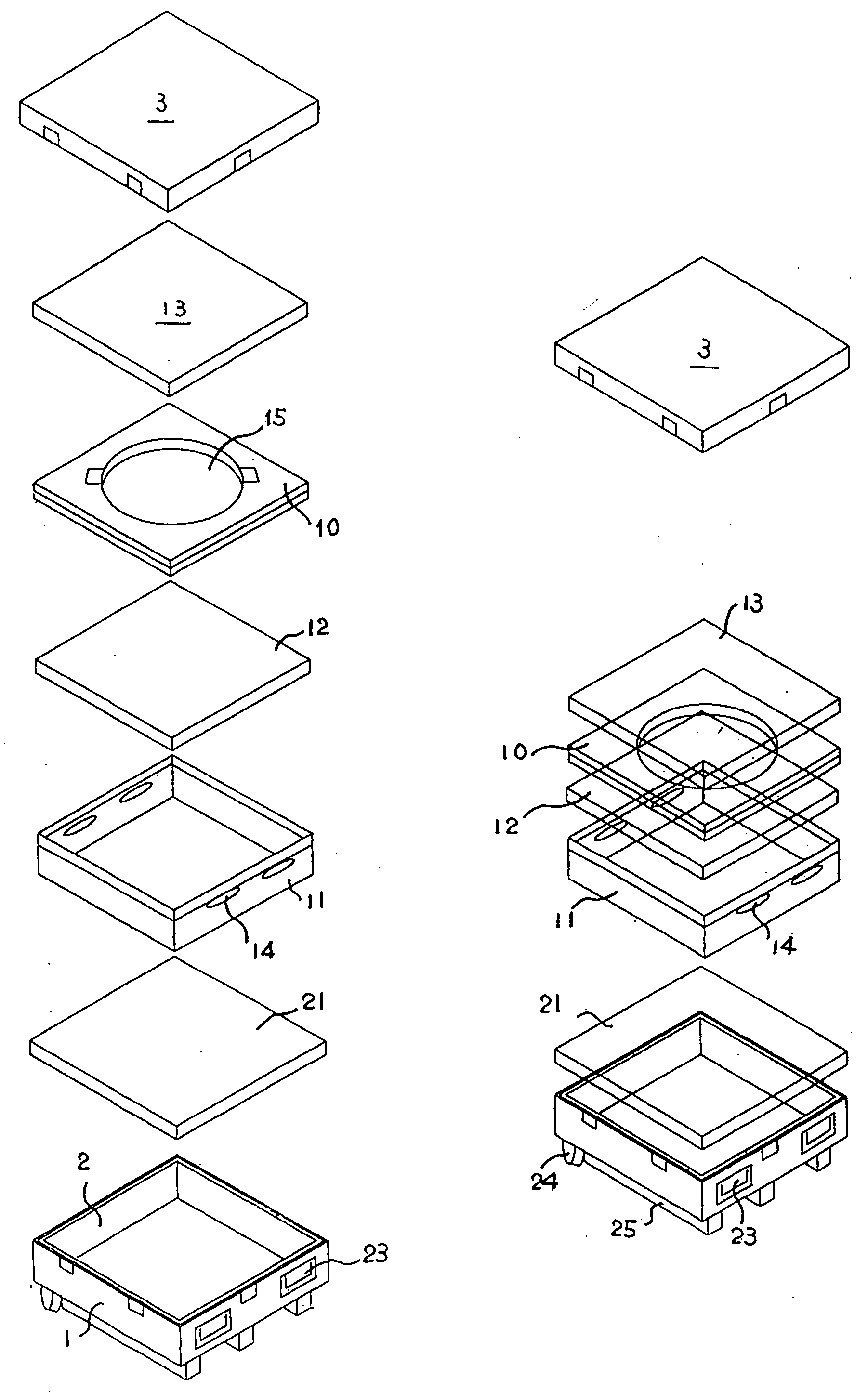
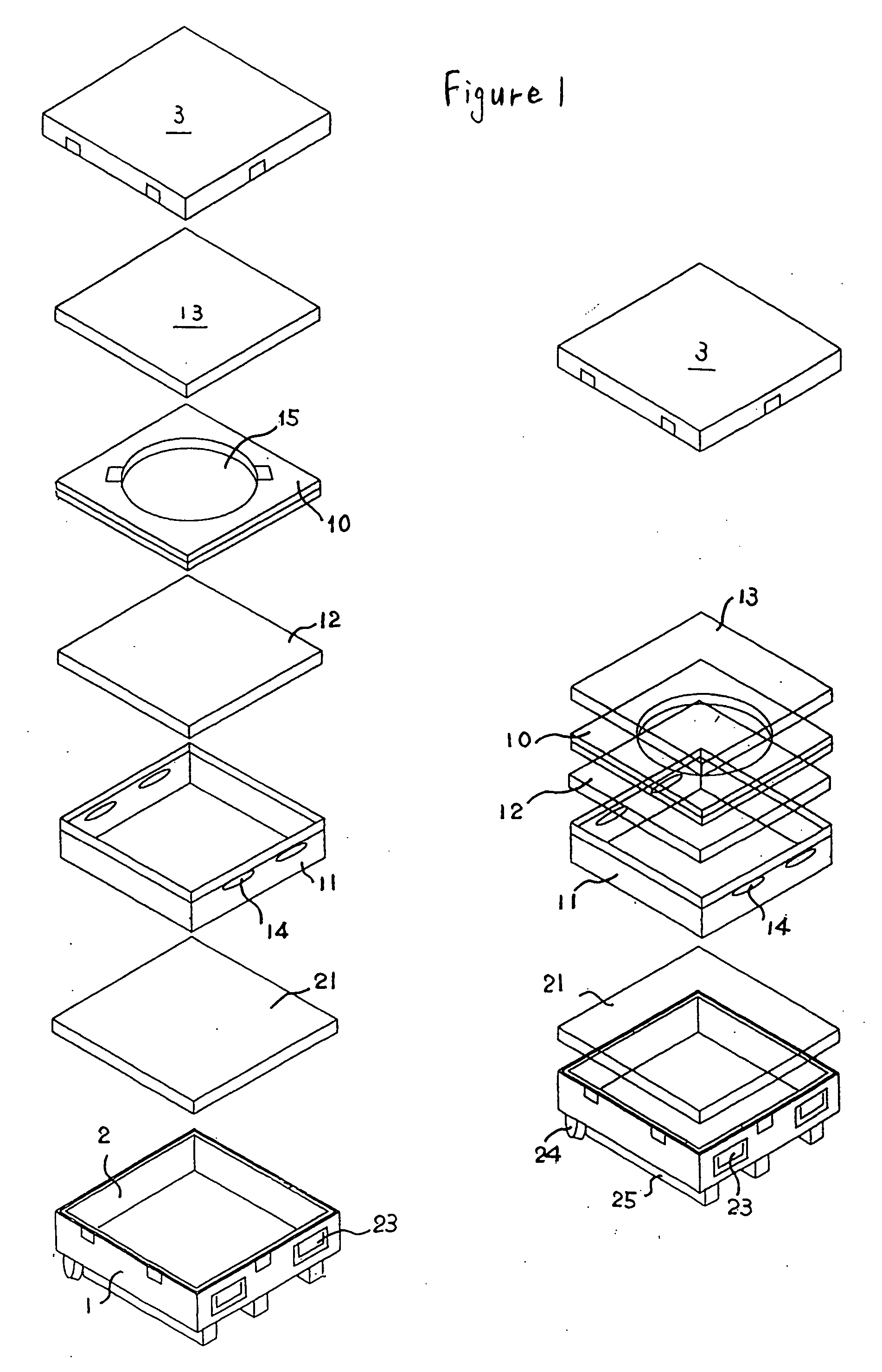
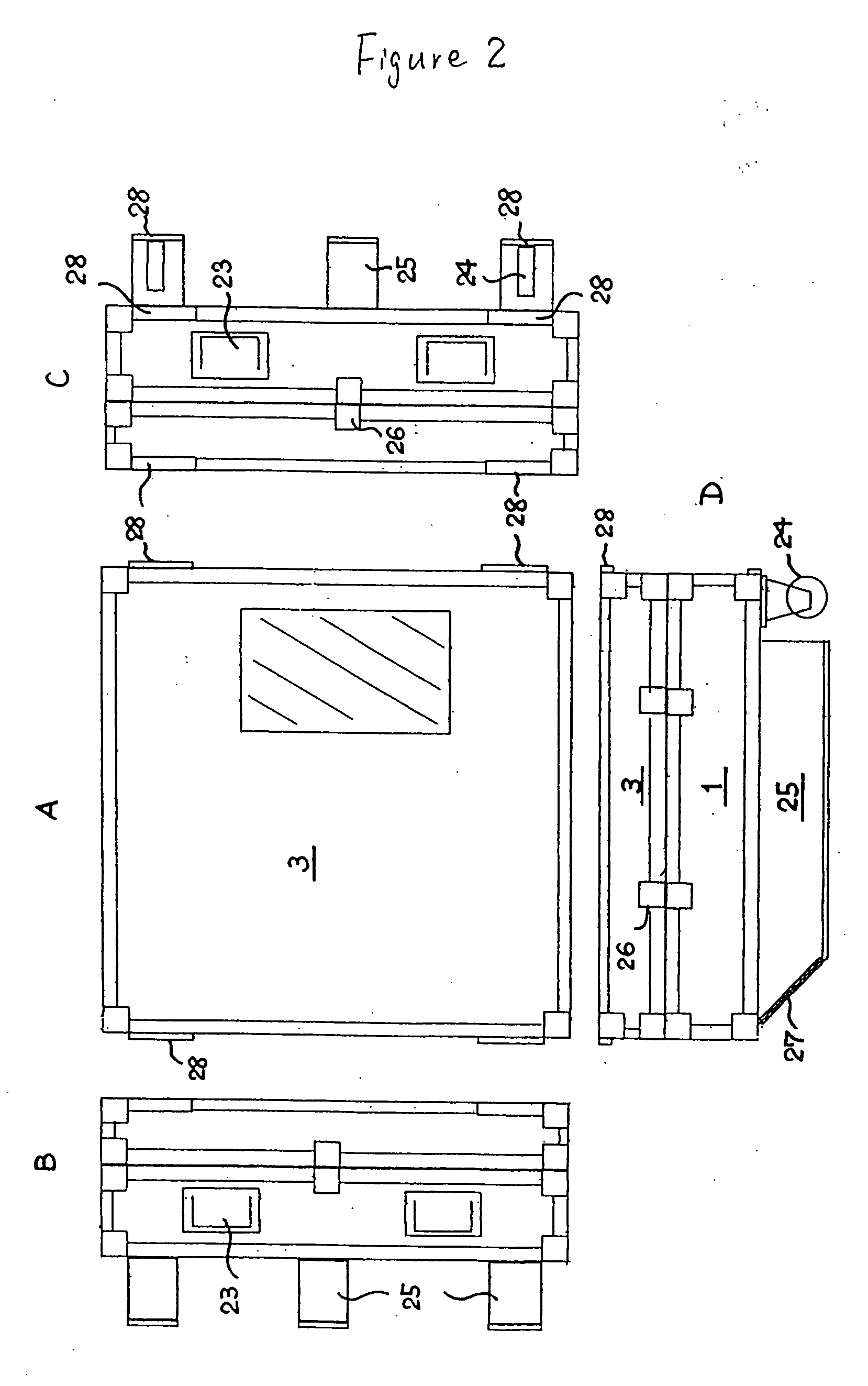
[0022] The sputtering target transport box of the present invention is, as illustrated in FIG. 1 and FIG. 2, a transport box comprising a void the size of a target, wherein supports 25 for mechanical transport are provided to the bottom plate of the transport box, and a wheel 24 for man-powered transport is provided to the edge portion of the bottom plate.

[0023] This transport box may be, as necessary, a double structure transport box structured from a plastic inner box 11 and an outer box 1 formed of aluminum, wood or a material in which plastic is affixed to such aluminum or wood. In addition, the transport box does not necessarily have to be a double structure, and may be a transport box structured from only the outer box 1 and an outer box cover 3. This may be suitably selected in accordance with the target to be handled.

[0024] In the case of a transport box structured from the inner box 11 and outer...


PUM

PropertyMeasurementUnit
Sizeaaaaaaaaaa
Electrical conductoraaaaaaaaaa

Abstract

The present invention pertains to a sputtering target transport box having a void the size of a sputtering target, wherein supports for mechanical transport are provided to the bottom plate of the transport box, and a wheel for man-powered transport is provided to the edge portion of the bottom plate. Provided thereby is a sputtering target transport box in which the removal and transport of a sputtering target is easy, and which enables the transport of a sputtering target without causing any damage thereto.

Description

TECHNICAL FIELD [0001] The present invention pertains to a sputtering target transport box in which the removal and transport of a sputtering target is easy, and which enables the transport of a sputtering target without causing any damage thereto. BACKGROUND ART [0002] Generally, a sputtering target employed in the manufacture of semiconductors and the like is gradually growing in size and becoming heavy, and demands for the flatness and surface cleansibility thereof are becoming increasingly tough. Further, in addition metal targets, some targets employ brittle materials such as ceramics, and needs are arising for safely transporting such targets from the target manufacturing plant to the workshop for forming thin films via sputtering with such targets. [0003] Since recent-day targets are highly purified, the unit production cost per target is increasing, and it causes the bigger loss in cost if such target is damaged or broken during its transport. [0004] Meanwhile, there are add...

Claims


Application Information

Patent Timeline
IPC IPC(8): B62B1/24B65D1/40B65D19/06B65D25/20B65D81/02B65D85/86C23C14/00C23C14/34H01L21/673
CPCH01L21/67724H01L21/67386
Inventor NEMOTO, FUMIYAINOUE, ATSUSHI
Owner JX NIPPON MINING& METALS CORP
Learn More