
Material stock advancing apparatus and method

a technology of material stock and advancing apparatus, which is applied in the direction of automatic conveying/guiding stock, turning machine accessories, manufacturing tools, etc., can solve the problems of inability to meet the timely demands and requirements of today's production shop, inability to program, and inability to meet the needs of the time-consuming and laborious operation of the production shop, so as to achieve the effect of increasing production capacity, facilitating versatility and flexibility, and substantial operating downtim

Inactive Publication Date: 2005-05-05
MOTL DANIEL WAYNE
View PDF16 Cites 2 Cited by
  • Summary
  • Abstract
  • Description
  • Claims
  • Application Information

AI Technical Summary

Benefits of technology

[0007] It is thus an object of the present invention to provide a low cost, non-complicated material advancing apparatus which may be reliably used in lieu of bar feeders of the type known in the art having ample storage capacities and automated features.
[0016] It is yet another object of the present invention to provide such a material advancing apparatus which accomplishes the foregoing and other objects and advantages and which is economical, durable, and fully effective in performing its intended functions.

Problems solved by technology

Although this approach may be suitable for CNC machining operations involving low production runs, it is most commonly employed with turning and milling machines lacking programmable capabilities, such as a manually operated lathe having chucking means made available for supporting and holding the workpiece during machining operations.
However, in some instances, the use of automated bar feeders of the type noted herein can be cost prohibitive in terms of capital investment, operating cost, downtime for changeover and adjustments, spatial requirements, and so forth.
Conversely, the simple placement and movement of material stock by operator means may fail to meet the timely demands and requirements of today's production shop.

Method used


Image

  • Material stock advancing apparatus and method
  • Material stock advancing apparatus and method
  • Material stock advancing apparatus and method

Examples


Embodiment Construction

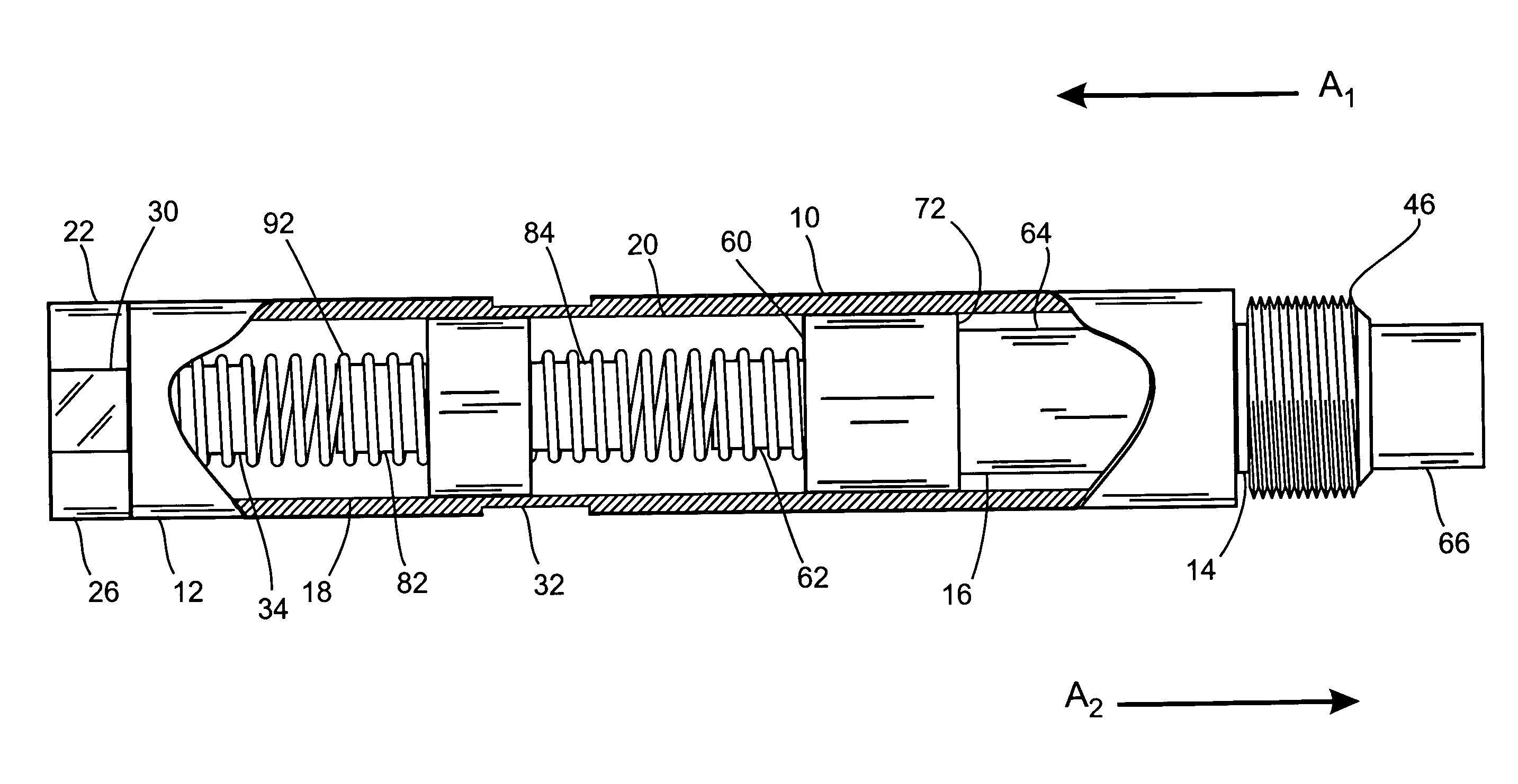
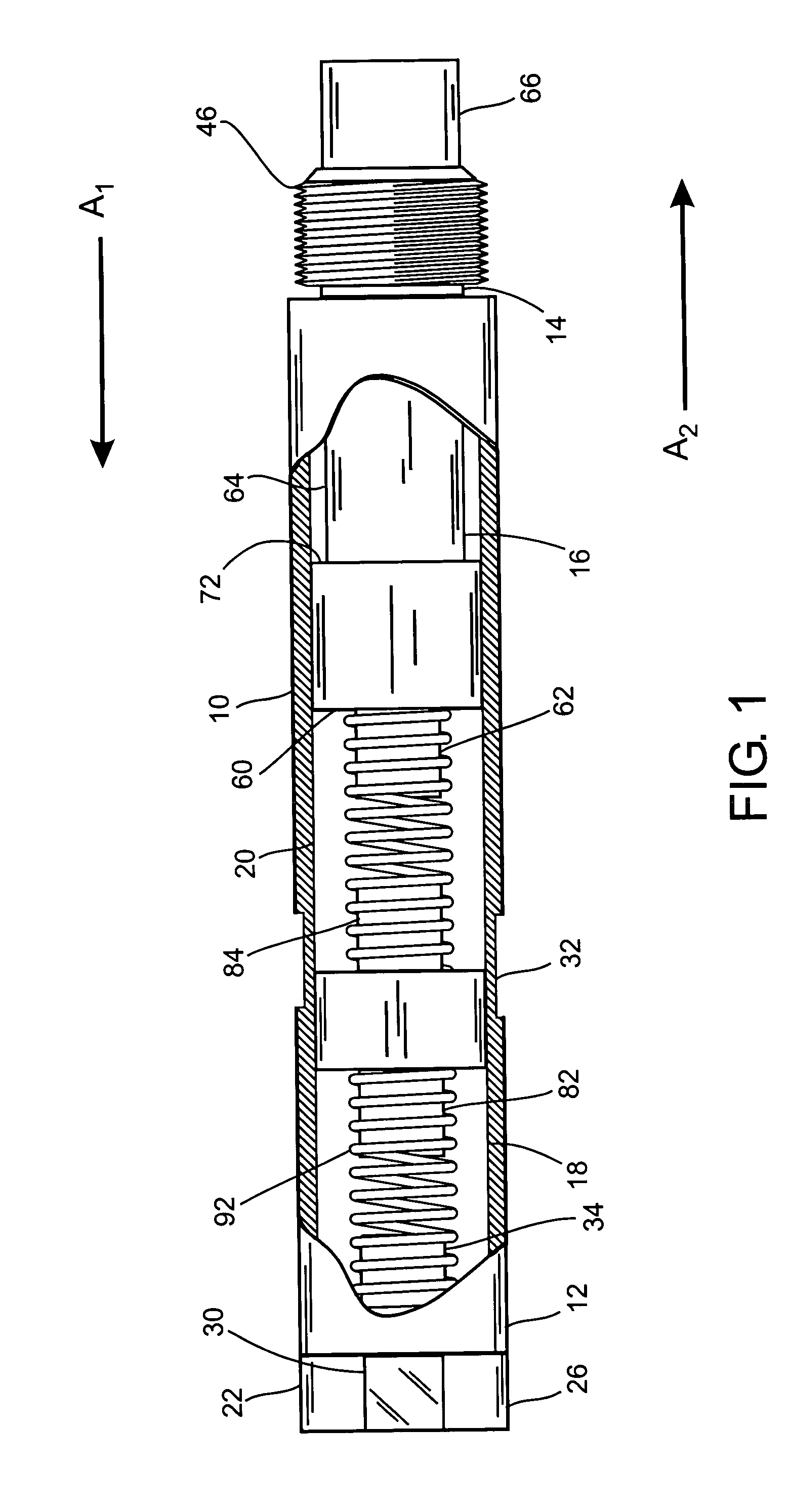
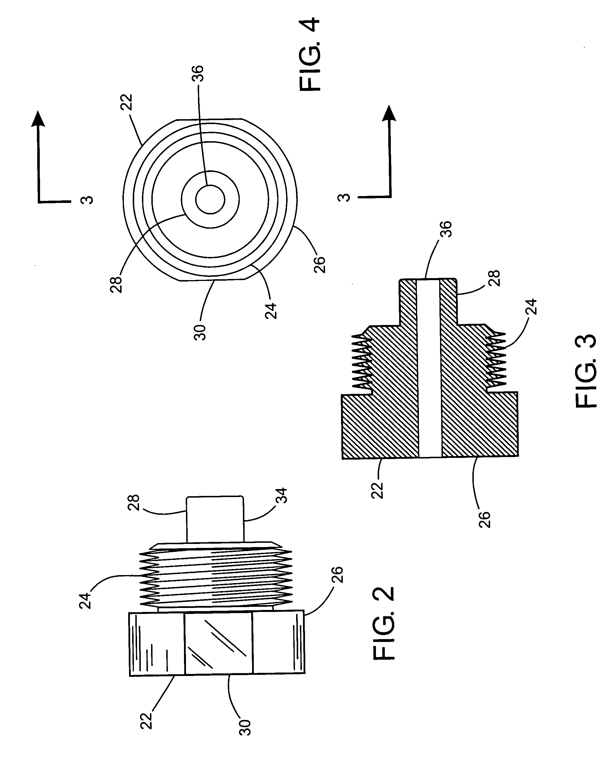
[0043] While this invention is susceptible of being embodied in many different forms, the preferred embodiment of the invention is illustrated in the accompanying drawings and described in detail hereinafter with the understanding that the present disclosure is to be considered to exemplify the principles of the present invention and is not intended to limit the invention to the embodiments illustrated and presented herein. The present invention has particular utility as an apparatus for advancing material stock into and through a headstock spindle assembly of a turning and milling machine having a computerized numeric controller or lacking programmable capacity, either means of which being available to permit machining of the material stock into a useful product.

[0044] Referring now to FIG. 1, there is shown generally at 10 an elongate body of cylindrical form having first and second ends 12, 14 and a plunger assembly 16 operatively working within and along the longitudinal axis o...


PUM

PropertyMeasurementUnit
diameteraaaaaaaaaa
geometric shapeaaaaaaaaaa
pressureaaaaaaaaaa

Abstract

A material stock advancing apparatus for use with a turning and milling machine having a computerized numeric controller or lacking programmable capabilities. The material stock advancing apparatus generally comprising an elongate body of cylindrical form having first and second ends and an interior chamber for housing therein a plunger assembly operably working therewithin. The second end comprising means for attaching the elongate body to an external holding device such as a collet or chuck adapter seated in a headstock spindle assembly. The first end comprising an end plug having a threaded section situated in between external and internal ends thereof, with the threaded section being threadably attached to the first end to permit the internal end to substantially engage a portion of the plunger assembly and ensure proper axial positioning of the plunger assembly during cyclic operation. The plunger assembly comprising a ram operably acting longitudinally within the interior chamber of the elongate body via biasing means comprising at least one spring operably acting in conjunction with controller means used in opening and closing the external holding device, which collectively controls the advancement of material stock toward and beyond the second end to permit the machining thereof for conversion into a useful product.

Description

FIELD OF THE INVENTION [0001] The present invention relates in general to an improved apparatus and method of advancing material stock during machining operations. More particularly, the present invention relates to an improved apparatus configurably arranged to cooperate with a headstock spindle assembly generally made part of a turning and milling machine, such as a stand-alone lathe operable with or without a computerized numeric controller. BACKGROUND OF THE INVENTION [0002] Computerized numerical controlled (CNC) machines are unique automated machines capable of forming small intricate end-use products from material stock with great precision and accuracy. As with all CNC machining operations, the ability to control output in terms of an acceptable finished product for the least amount of cost is of the utmost importance to today's production shop. To realize this goal as well as others, the CNC machine is typically fine tuned to the extent of programming the controller for int...

Claims


Application Information

Patent Timeline
Patent Type & Authority Applications(United States)
IPC IPC(8): B23B13/00B23B13/02
CPCB23B13/021Y10T82/2518Y10T82/26Y10T82/2514Y10T82/2521
Inventor MOTL, DANIEL WAYNE
Owner MOTL DANIEL WAYNE
Learn More